In the world of electronics, tiny components like capacitors play a crucial role in shaping how devices function. Among these, 'capacitor 102' is a common marking that often puzzles beginners and seasoned engineers alike. Much like how different ingredients in a recipe bring a dish to life, capacitors with specific values like 102 perform different functions in electronic circuits. This article will demystify capacitor 102, explaining its value, decoding the code, and exploring its common applications, making the sometimes intimidating world of electronic components a little more straightforward.
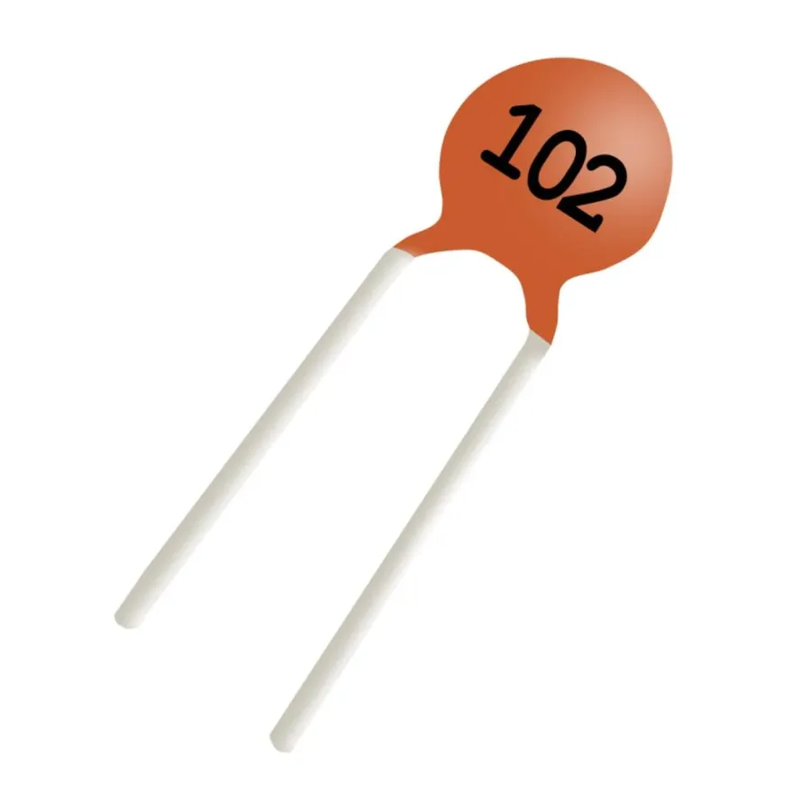
The '102' marking on a capacitor is a standardized numerical code that denotes its capacitance value, crucial for understanding its role in electronic circuits. This code is part of a widely adopted 3-digit system where the first two digits represent the significant figures, and the third digit indicates the multiplier, which is a power of ten. By understanding this system, engineers and hobbyists can quickly determine the capacitance of a component without the need for direct measurement.
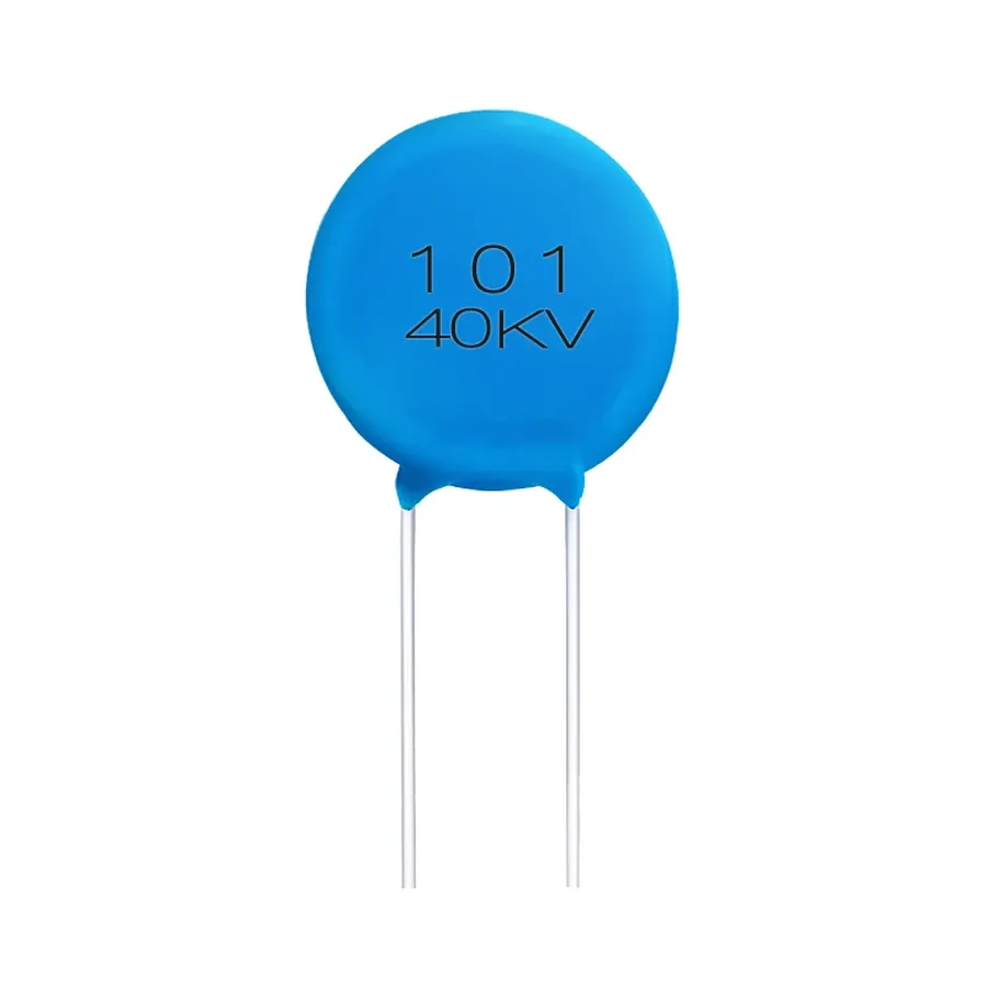
The '102' marking on a capacitor signifies its capacitance value using a standardized three-digit code. This code translates directly to picofarads (pF), a unit often used for small capacitance values. Understanding this conversion is fundamental to selecting the appropriate capacitor for any application. The first two digits indicate the significant figures of the capacitance value, and the third digit represents the multiplier, which is a power of ten.
| Digit | Meaning | Example |
|---|---|---|
| 102 | 10 x 10^2 pF | 10 x 100 = 1000 pF |
| 103 | 10 x 10^3 pF | 10 x 1000 = 10,000 pF |
| 104 | 10 x 10^4 pF | 10 x 10,000 = 100,000 pF |
In the case of '102', the code is interpreted as 10 multiplied by 10 to the power of 2 (10 x 10²). This calculation yields 1000 picofarads (pF). Since picofarads are often inconvenient for practical use, it's helpful to convert this to larger units, like nanofarads (nF) or microfarads (µF). A 1000 pF is equal to 1 nanofarad (nF).
| Unit | Value in Farads (F) | Value in relation to 102 capacitor |
|---|---|---|
| Picofarad (pF) | 10^-12 F | 1000 pF |
| Nanofarad (nF) | 10^-9 F | 1 nF |
| Microfarad (µF) | 10^-6 F | 0.001 µF |
Therefore, a capacitor marked '102' has a capacitance of 1000 pF, which is equivalent to 1 nF or 0.001 µF. This precise conversion is essential for correctly interpreting capacitor specifications in electronic circuits.
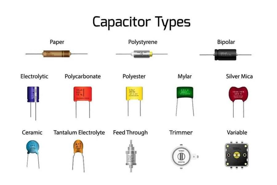
Understanding the '102' code on a capacitor becomes clearer when compared to other common codes like '103' and '104'. These numerical codes represent capacitance values in picofarads (pF) using a standard three-digit system, where the first two digits are significant figures, and the third is the multiplier (power of 10). This section will illustrate the conversions for these codes to microfarads (µF) to provide a better understanding of the relative values.
| Capacitor Code | Calculation | Value in pF | Value in nF | Value in µF |
|---|---|---|---|---|
| 102 | 10 x 10^2 pF | 1000 pF | 1 nF | 0.001 µF |
| 103 | 10 x 10^3 pF | 10,000 pF | 10 nF | 0.01 µF |
| 104 | 10 x 10^4 pF | 100,000 pF | 100 nF | 0.1 µF |
As the table demonstrates, each increment in the third digit of the code results in a tenfold increase in capacitance. For example, a '103' capacitor has ten times the capacitance of a '102' capacitor, and a '104' has ten times the capacitance of the '103' capacitor. These values can also be converted to microfarads (µF) by dividing by 1,000,000.
The conversion from picofarads (pF) to microfarads (µF) is essential because microfarads are commonly used for expressing larger capacitance values. The formulas for these conversions are as follows: 1 nF = 1000 pF, and 1 µF = 1000 nF = 1,000,000 pF. This allows one to easily move between the three common units of capacitance.
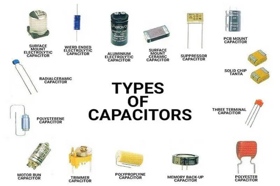
While the '102' marking primarily denotes a capacitance value, it's crucial to recognize that this value can be found across various capacitor types, each with its unique construction, properties, and optimal application scenarios. The 102 designation primarily signifies a 1000 picofarad (pF) or 1 nanofarad (nF) capacitance, but the type of capacitor significantly affects its performance characteristics.
| Capacitor Type | Description | Typical Applications | Advantages | Disadvantages |
|---|---|---|---|---|
| Multilayer Ceramic (MLCC) | Consists of multiple layers of ceramic dielectric material and metal electrodes. | Bypass filtering, decoupling, general-purpose applications | Small size, low cost, wide range of values, good high-frequency performance | Can be susceptible to cracking, may exhibit capacitance variation with temperature and voltage, limited voltage rating |
| Ceramic Disc | A single disc of ceramic material is used as the dielectric. | General-purpose applications, lower frequency circuits | Low cost, good stability for temperature changes | Larger physical size compared to MLCCs |
| Film Capacitors | Uses a thin plastic film as the dielectric material. | High-voltage applications, timing circuits, audio applications | High stability, low loss, high voltage and current handling, stable capacitance over temperature | Larger physical size, higher cost |
| Tantalum Capacitors | Uses tantalum pentoxide as the dielectric material. | Filtering, power supply decoupling where high capacitance is needed | High capacitance in small size | Sensitive to overvoltage, higher cost, may not handle high inrush current well |
| Electrolytic Capacitors | Uses a liquid or gel electrolyte to form a dielectric. | Power supply filtering, energy storage | High capacitance values | Polarized, limited frequency response, relatively short lifespan, leakage |
Specifically regarding the '102' designation, it is most commonly found in multilayer ceramic capacitors (MLCCs), particularly those in the form of small disc capacitors. These capacitors are prevalent in consumer electronics due to their small size, reliability, and cost-effectiveness. However, film capacitors may also be found with a '102' marking where higher stability and precision are required. The choice of capacitor type depends heavily on the application requirements, especially concerning voltage, temperature, and frequency response.
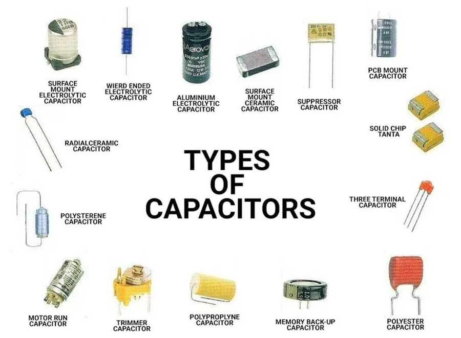
Capacitors marked with '102', representing a capacitance of 1000 pF or 1 nF, are ubiquitous in electronic circuits due to their effectiveness in various roles, primarily in filtering, decoupling, and timing applications. Their small size and reliable performance make them suitable for a wide range of uses from simple hobby projects to complex industrial systems.
A common example is their usage in microcontrollers where the 102 capacitor is used for both power supply decoupling at the power pins to ensure stable operation, and also in the oscillator circuit to provide the necessary timing for the clock. Another example would be in audio applications, such as in pre-amplifiers, to isolate the DC biasing of a previous stage. In consumer electronics, these capacitors are found in nearly all devices.
This section addresses common questions about '102' capacitors, providing clear and concise answers to aid understanding and practical application, covering topics from the meaning of the '102' code to the differences between various capacitor types and their characteristics.
Selecting the appropriate '102' capacitor for a given application necessitates a thorough understanding of its electrical characteristics and how they align with the project's requirements. Key factors such as voltage rating, tolerance, temperature coefficient, and dielectric material properties play a vital role in ensuring optimal circuit performance and reliability. This section outlines these considerations to guide engineers in selecting suitable capacitor 102 components.
| Characteristic | Description | Importance for Capacitor 102 |
|---|---|---|
| Voltage Rating | The maximum voltage that a capacitor can safely withstand without damage or failure. | Essential to prevent dielectric breakdown. Select a voltage rating significantly higher than the operating voltage. |
| Capacitance Tolerance | The permissible variation in the actual capacitance value from its nominal (1000 pF) value. | Determines how closely the capacitor's actual value matches the desired capacitance. Critical in timing and filtering circuits. |
| Temperature Coefficient | Describes how much the capacitance changes with temperature variations. | Affects the capacitance in different operating conditions, particularly in harsh environments, thus impacting circuit stability and precision. Choose a temperature coefficient that suits the temperature range in which the capacitor will operate. |
| Dielectric Material | The insulating material between the capacitor's electrodes. | Influences characteristics such as temperature stability, voltage coefficient and dissipation factor. Common dielectrics for '102' capacitors include ceramic (NP0, X7R, Y5V) and their selection is application specific. |
| Physical Size and Package | The physical dimensions and mounting style of the capacitor. | Critical for PCB layout and space constraints. Choose a package size that is compatible with the application. |
Selecting a '102' capacitor involves more than just its capacitance value. By carefully considering the voltage rating, capacitance tolerance, temperature coefficient, dielectric material, and physical size you can ensure optimal performance and longevity in electronic applications. Always prioritize selecting components that not only meet but exceed the maximum operating conditions of your electronic circuit.
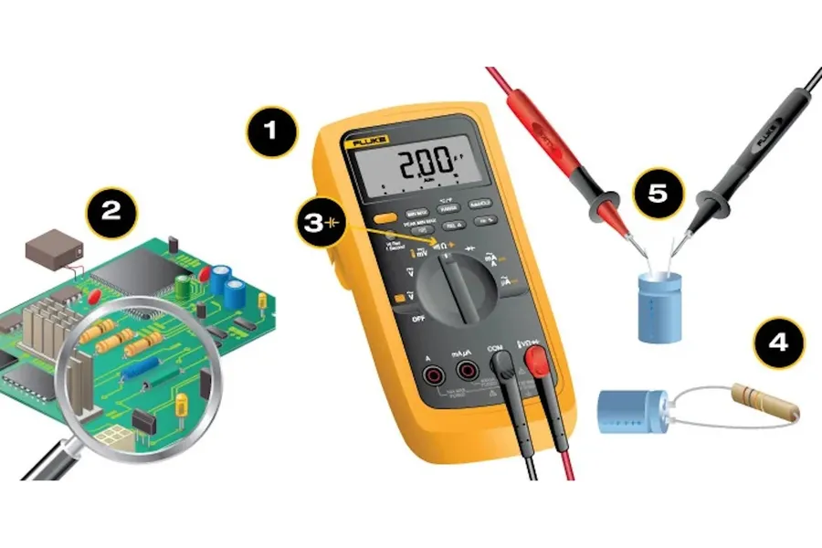
Capacitor failure can significantly impact circuit performance; therefore, proper troubleshooting and testing are crucial. This section provides a guide on how to use a multimeter to verify the functionality of a '102' capacitor, identify common failure modes, and interpret test results.
Capacitor 102, a tiny component with a big impact, plays a key role in countless electronic devices. Understanding its value, the decoding method, and its common applications is a foundational knowledge for any electronics enthusiast or professional. The capacitor 102, while seemingly small, is an integral part of many electronic designs. Its precise 1000 pF (or 1 nF) value allows it to perform a range of critical functions, from filtering noise to timing circuits. By having an understanding of how to decode these numbers, anyone can increase their knowledge of the intricacies of electronics, and how these small components create such a great impact. This guide helps clear up the confusion and demystifies this important electronic component.

