Imagine a bustling city with electrical currents flowing like cars on a highway. Now, picture a traffic controller – that's [a resistor]. It's a seemingly simple component but crucial in electronics, managing the flow of electricity and ensuring circuits function correctly. This article unravels the mysteries of resistors, making their role clear and straightforward, like an easily navigable map.
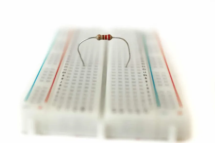
A resistor is a fundamental passive electronic component designed to impede the flow of electrical current, analogous to a gatekeeper in a circuit. It introduces a specific amount of electrical resistance, measured in Ohms (Ω), which restricts the current while transforming a portion of the electrical energy into heat. This controlled restriction is crucial for managing current and voltage levels within a circuit, enabling precise control and operation of electronic devices.
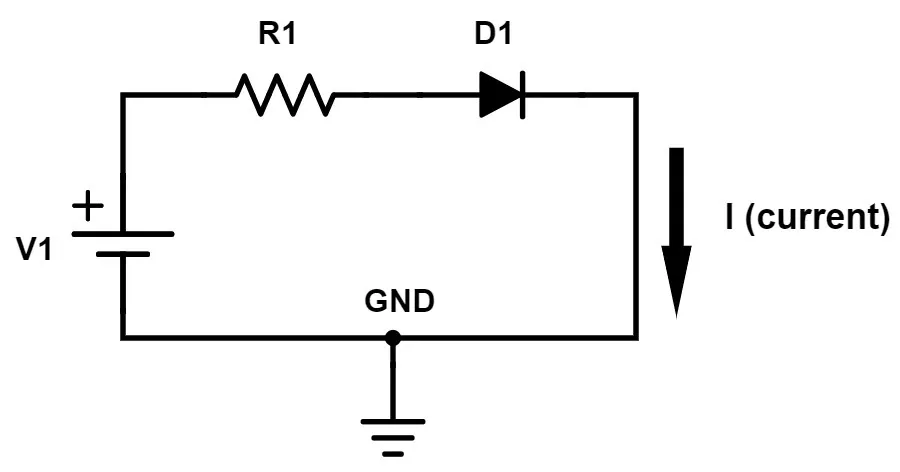
Resistors function by impeding the flow of electrical current, transforming electrical energy into heat through a process akin to friction. This opposition to current flow, known as resistance, is a fundamental property of the material the resistor is made from and its physical dimensions. The magnitude of resistance is measured in Ohms (Ω), and the energy dissipation manifests as heat, which is a direct consequence of the collisions between the charge carriers (electrons) and the atoms within the resistor's structure.
The degree of resistance is primarily determined by three factors: the material's resistivity, the length of the resistor, and the cross-sectional area through which current flows. Materials with higher resistivity naturally offer more resistance, while longer resistors exhibit greater overall resistance, and thicker resistors have lower resistance, similar to how a wider pipe allows more water to flow. By carefully controlling these parameters, resistors can be engineered to provide precise levels of resistance, allowing engineers to control current and voltage levels within electronic circuits.
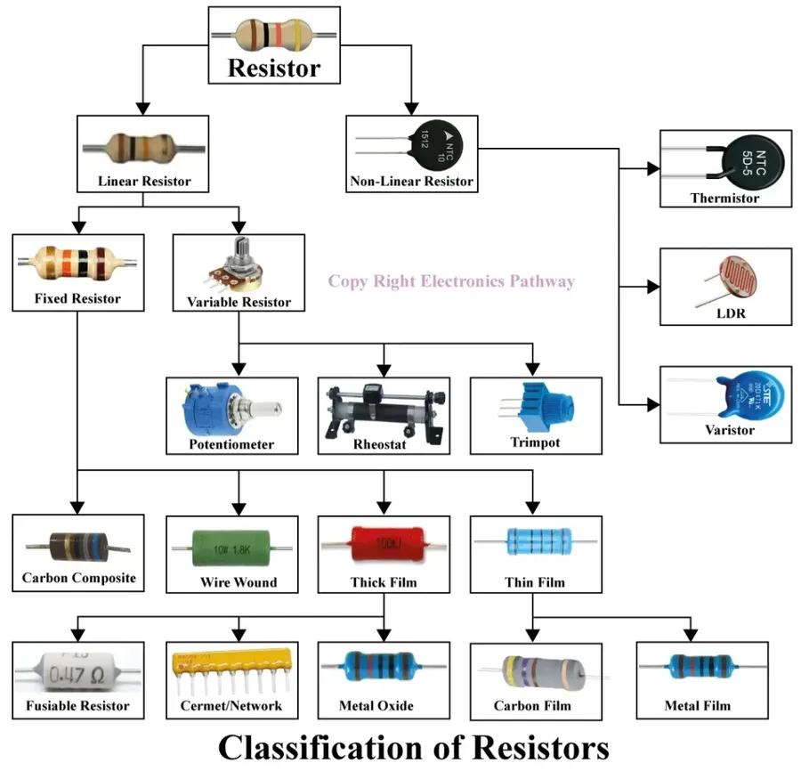
Resistors, while fundamentally providing resistance to current flow, come in various forms, each designed for specific applications and exhibiting unique characteristics. This section categorizes and details these types, including fixed, variable, and special purpose resistors, providing insight into their construction, properties, and common uses.
| Resistor Type | Description | Construction | Applications | Advantages | Disadvantages |
|---|---|---|---|---|---|
| Fixed Resistors | Resistors with a single, unchangeable resistance value. | Varying materials such as carbon film, metal film, or wire wound around a ceramic core. | General purpose electronics, circuit boards, power supplies. | Low cost, reliable, wide availability. | Fixed resistance value, not adjustable. |
| Carbon Film Resistors | Fixed resistors with a thin carbon film deposited on an insulator. | Thin layer of carbon on ceramic substrate, with terminals. | General purpose circuits, low power applications. | Low cost, good stability at low temperatures. | Lower precision and higher noise compared to metal film. |
| Metal Film Resistors | Fixed resistors with a thin metal film deposited on an insulator. | Thin layer of metal alloy on ceramic substrate, with terminals. | Precision circuits, instrumentation. | High precision, low noise, good temperature stability. | More expensive than carbon film. |
| Wirewound Resistors | Fixed resistors with a resistive wire wound around an insulating core. | Wire of resistive alloy wound around a ceramic core | High power circuits, precision measurement. | High power handling capability, precise resistance values. | Larger size, can be inductive, more costly. |
| Variable Resistors | Resistors whose resistance value can be changed manually. | A resistive element with a wiper that moves along the element. | Volume control, lighting control, calibration circuits. | Adjustable resistance, flexible circuit design. | Less precise than fixed resistors, susceptible to wear. |
| Potentiometers | Three-terminal variable resistors used for adjustable voltage division. | A resistive track with a sliding contact that moves along it. | Volume controls, voltage dividers, sensor adjustments. | Adjustable output voltage, widely available. | Limited power rating, rotational or linear travel limits. |
| Rheostats | Two-terminal variable resistors used for adjusting current. | A resistive element with a sliding contact. | Current limiting in circuits, motor speed control. | High power handling capability, current control. | Not as precise as potentiometers, less common. |
| Special Resistors | Resistors with resistance that changes based on external conditions. | Made of materials that respond to temperature, light, or magnetic fields. | Sensor circuits, temperature compensation, light detectors. | Provide dynamic control and adaptability. | May have limited linear range, can be less stable than fixed resistors. |
| Thermistors | Resistors whose resistance changes with temperature. | Semiconductor material that exhibits large change in resistance with temperature. | Temperature sensing, temperature compensation. | High sensitivity to temperature, compact size. | Non-linear temperature response, can be limited temperature range. |
| Photoresistors | Resistors whose resistance changes with light intensity. | Semiconductor material whose conductivity increases with light exposure. | Light sensing, ambient light detection. | Sensitive to light, simple to implement. | Non-linear response to light, slow response. |
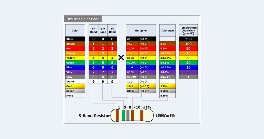
Resistor color codes provide a standardized method for identifying a resistor's resistance value and tolerance. These color bands, typically 4 to 6 in number, are printed directly on the resistor body and allow for quick determination of its electrical characteristics without requiring specialized measuring equipment.
| Color | 1st Band (Digit) | 2nd Band (Digit) | 3rd Band (Multiplier) | 4th Band (Tolerance) | 5th Band (Temp. Coefficient) | 6th Band (Reliability) |
|---|---|---|---|---|---|---|
| Black | 0 | 0 | 1 (10⁰) | |||
| Brown | 1 | 1 | 10 (10¹) | ±1% | 100 ppm/°C | 1% |
| Red | 2 | 2 | 100 (10²) | ±2% | 50 ppm/°C | 0.1% |
| Orange | 3 | 3 | 1,000 (10³) | 15 ppm/°C | ||
| Yellow | 4 | 4 | 10,000 (10⁴) | 25 ppm/°C | ||
| Green | 5 | 5 | 100,000 (10⁵) | ±0.5% | ||
| Blue | 6 | 6 | 1,000,000 (10⁶) | ±0.25% | ||
| Violet | 7 | 7 | 10,000,000 (10⁷) | ±0.1% | ||
| Grey | 8 | 8 | ±0.05% | |||
| White | 9 | 9 | ||||
| Gold | 0.1 (10⁻¹) | ±5% | ||||
| Silver | 0.01 (10⁻²) | ±10% | ||||
| None | ±20% |
To decode a resistor, read the bands from left to right, starting with the band closest to the edge of the resistor. The first two bands represent significant digits of the resistance value. The third band acts as a multiplier, indicating the power of ten by which to multiply the first two digits. The fourth band signifies the tolerance of the resistor, showing the percentage of deviation allowed from the nominal resistance value. Some resistors include a fifth band which indicates the temperature coefficient, representing change in resistance value per degree Celsius. A sixth band is sometimes included to indicate the resistor's reliability rating. For example, a resistor with bands of Red, Violet, Brown, and Gold would be 27 * 10^1 ohms with a 5% tolerance, so 270 ohms +/- 5%.
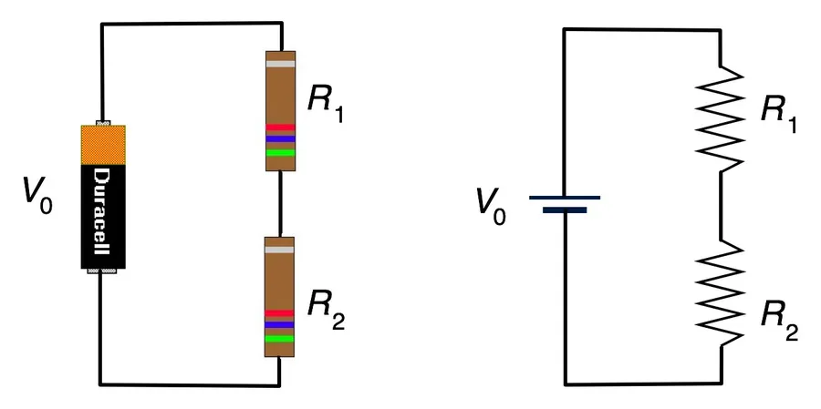
Resistors are fundamental components in electrical circuits, and their behavior changes depending on how they are connected. Understanding series and parallel configurations is critical for analyzing and designing circuits. In a series connection, resistors are placed end-to-end, forming a single path for current flow. Conversely, in a parallel connection, resistors are placed side-by-side, providing multiple paths for current.
| Characteristic | Series Connection | Parallel Connection |
|---|---|---|
| Current | Same through all resistors | Divides between branches |
| Voltage | Divides across resistors | Same across all resistors |
| Total Resistance | Sum of individual resistances (R_total = R1 + R2 + ...) | Reciprocal of sum of reciprocal resistances (1/R_total = 1/R1 + 1/R2 + ...) |
| Effect of Adding Resistor | Increases total resistance | Decreases total resistance |
In a series circuit, the current has only one path to follow, meaning that the same current flows through each resistor. However, the voltage is divided across each resistor, with the sum of the voltage drops equalling the source voltage. The total resistance in a series circuit is simply the sum of all individual resistances. In contrast, a parallel circuit provides multiple paths for current flow, and the current divides among these paths. The voltage across each resistor is the same, and the total resistance is less than that of the smallest individual resistor. These differences in electrical behavior have significant implications in circuit design.
The formulas below show how to calculate total resistance for series and parallel circuits. Understanding how to apply these formulas allows engineers to accurately calculate current flow and voltage drops in circuits, which is essential for proper design and troubleshooting. This also highlights the importance of circuit design and planning.
R_{total\ series} = R_1 + R_2 + R_3 + ... + R_n
\frac{1}{R_{total\ parallel}} = \frac{1}{R_1} + \frac{1}{R_2} + \frac{1}{R_3} + ... + \frac{1}{R_n}
Consider the example of two 10 Ohm resistors connected in series. The total resistance would be 20 Ohms. If the same two 10 Ohm resistors were placed in parallel, the total resistance would be 5 Ohms. These simple examples show the impact the connection type has on the overall resistance of a circuit. Engineers use this effect to control the total current and voltage distribution throughout complex circuits. The accurate calculation of this total resistance is key to circuit planning and function.
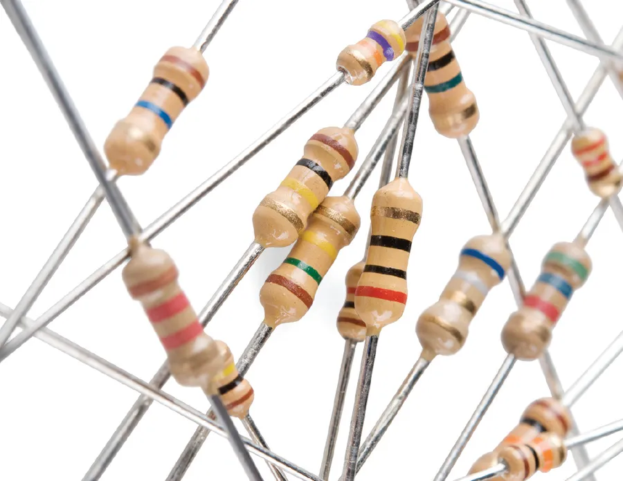
Resistors, seemingly simple components, are ubiquitous in modern technology, playing a vital role in the functionality of countless devices. Their primary function of impeding current flow is the foundation for controlling electrical behavior in nearly every electronic circuit.
Here are some real-world examples highlighting the diverse applications of resistors:
This section addresses common queries regarding resistors, clarifying their function, practical applications, and impact on voltage within electrical circuits. We aim to provide clear and concise answers to help build a foundational understanding of these essential electronic components.
Selecting the appropriate resistor for a given application is critical for ensuring circuit functionality and longevity. Several factors must be considered, including resistance value, tolerance, power rating, and resistor type. These parameters directly impact a circuit’s behavior and its ability to perform its intended function. Choosing incorrectly can result in circuit malfunction, component failure, or even safety hazards.
| Factor | Description | Importance |
|---|---|---|
| Resistance Value | The opposition to current flow, measured in ohms (Ω). | Determines the current flow in the circuit. Needs to be accurate based on the design calculations. |
| Tolerance | The allowable deviation of the actual resistance value from the marked value. | Affects precision in current and voltage control. Choose lower tolerance for precision applications. |
| Power Rating | The maximum power the resistor can dissipate safely, measured in watts (W). | Prevents the resistor from overheating and failing. Should be greater than the power it will dissipate. |
| Resistor Type | Different types have different properties (e.g., carbon film, metal film, wirewound). | Affects stability, temperature coefficient, and noise characteristics. Select based on requirements of application. |
When selecting a resistor, always verify that the power rating is sufficient for the expected power dissipation in the circuit. The power dissipated by a resistor can be calculated using the formula P = I²R or P = V²/R, where P is power in watts, I is current in amps, R is resistance in ohms, and V is voltage in volts. Exceeding the power rating may cause the resistor to overheat, potentially leading to damage or failure of the component and possibly other parts of the circuit. A safety margin, usually a rating at least twice the expected power dissipation, should always be allowed.
Here are some tips when selecting resistors in circuit design: 1. **Start with Design Calculations:** Always determine the required resistance value by analyzing the circuit needs. 2. **Consider Accuracy:** Choose tolerance based on the precision needed in your application, such as 1%, 5%, or 10%. 3. **Think about Stability:** Metal film resistors are more stable than carbon film resistors and therefore are a better choice for precision circuits. 4. **Understand Thermal Stress:** Ensure the power rating of your resistor is significantly higher than what it is expected to dissipate. 5. **Take Physical Size Into Account:** Resistors with higher power ratings are physically larger so will require more space in your circuit design. 6. **Match the Type to Application:** Wirewound resistors are good for high power, metal film for precise circuits, and carbon film are ideal for general purpose usage.
Resistors play a critical role in advanced circuit designs, extending beyond simple current limiting to shaping signal characteristics and establishing precise voltage levels. Their behavior in complex configurations like filters and voltage dividers is essential for achieving sophisticated electronic functionalities.
In filter circuits, resistors, in conjunction with capacitors or inductors, are instrumental in frequency selection, enabling circuits to pass or block specific frequency ranges. This capability is crucial in audio processing, communication systems, and many other applications that require selective signal processing. For example, a low-pass filter would use a resistor and a capacitor to allow low-frequency signals to pass while blocking high-frequency signals.
Voltage dividers, another common advanced application, utilize resistors to step down or divide a voltage into smaller, usable levels. These are essential for circuits that require different voltage levels for various components and serve as a basic building block of many electronic circuits. The output voltage is a proportion of the input voltage, determined by the ratio of the resistors used in the divider.
Beyond these, resistors are crucial in amplifier circuits for gain setting, and biasing transistors for optimal operation and also play key roles in feedback networks for system stabilization and also used for creating specific current characteristics for various applications. The strategic use of resistors, therefore, extends far beyond simple current regulation to provide fundamental support for advanced electronic design.
Understanding the behavior of resistors in these complex scenarios requires a solid grasp of basic circuit laws, such as Ohm's Law and Kirchhoff's Laws and an appreciation of how the component's specifications interact within the circuit to achieve the intended function, further proving the need to understand the material's properties, temperature coefficient, and tolerance for various applications.
From the humble traffic controller to vital components in complex systems, resistors play an essential role in the world of electronics. Understanding their function, types, and applications is crucial for anyone involved with electrical circuits. This article provides the foundational knowledge to understand how a resistor affects electrical current flow, allowing readers to move from basic understanding to practical applications, highlighting the importance of resistors in our increasingly electronic world, just like the traffic controller that keeps cars flowing smoothly, resistors keep our electrical circuits running smoothly.

