Capacitors are fundamental components in electronics, storing energy and facilitating circuit operations. A common marking, '105' on a capacitor, often perplexes many. This article unravels the mystery behind the '105' marking, focusing specifically on the capacitor 105, its value, and its various applications. By connecting this technical detail to real-world applications, we aim to illuminate the crucial role such components play in modern technology.
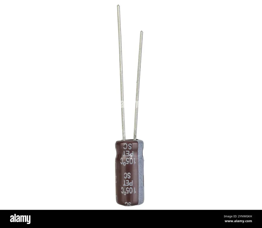
The marking '105' on a capacitor is a standardized three-digit code that indicates its capacitance value, using a method that converts the code into a picofarad (pF) value. This system allows manufacturers to label small components with a clear indication of their electrical property. This system is particularly useful for small components where printing full values is not practical.
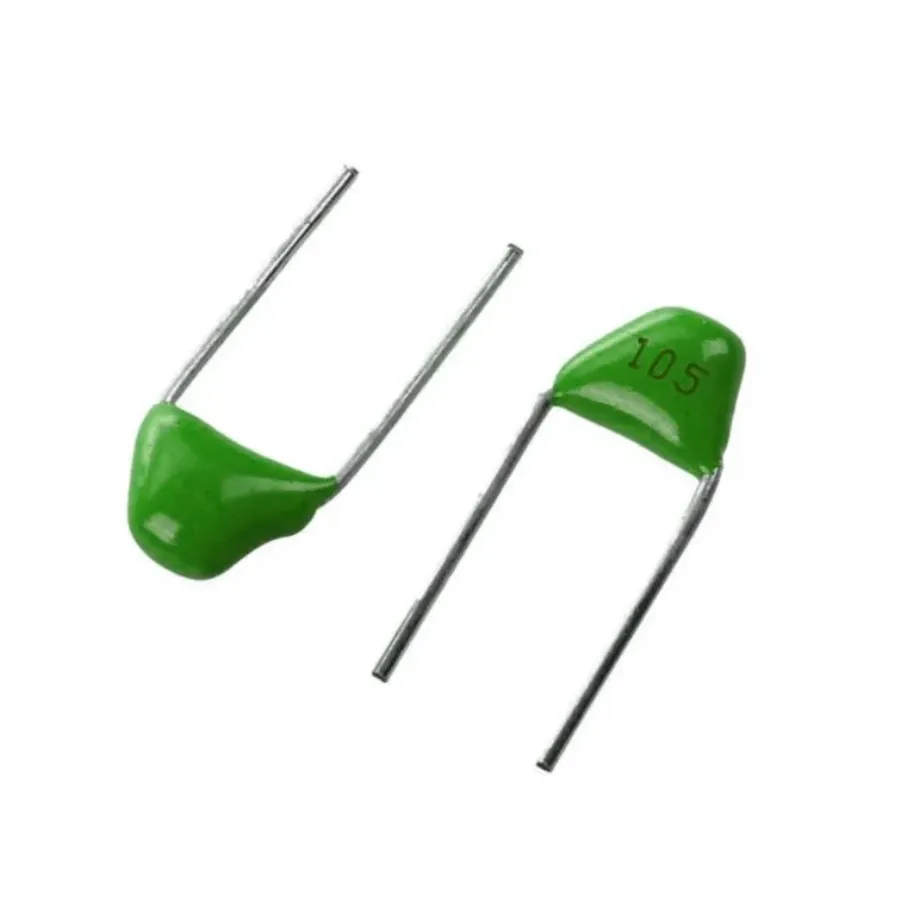
The '105' marking on a capacitor is a standardized three-digit code that directly indicates its capacitance value. This system is crucial for easily identifying the electrical storage capacity of the component, which is essential for circuit design and repair.
The first two digits of the code represent the significant figures, and the third digit is the multiplier. Specifically, the code '105' translates to 10 x 10^5 picofarads (pF). To calculate the capacitance in more common units, such as microfarads (µF), a conversion is needed.
| Code Digit | Meaning | Calculation | Result |
|---|---|---|---|
| 10 | Significant Figures | - | 10 |
| 5 | Multiplier | 10^5 | 100,000 |
| 105 | Capacitance in pF | 10 x 10^5 pF | 1,000,000 pF |
| 105 | Capacitance in uF | 1,000,000 pF / 1,000,000 | 1 µF |
Therefore, a capacitor marked '105' has a capacitance of 1,000,000 pF, which is equivalent to 1 µF. Understanding this code ensures the correct component is selected for the intended electronic circuit function.
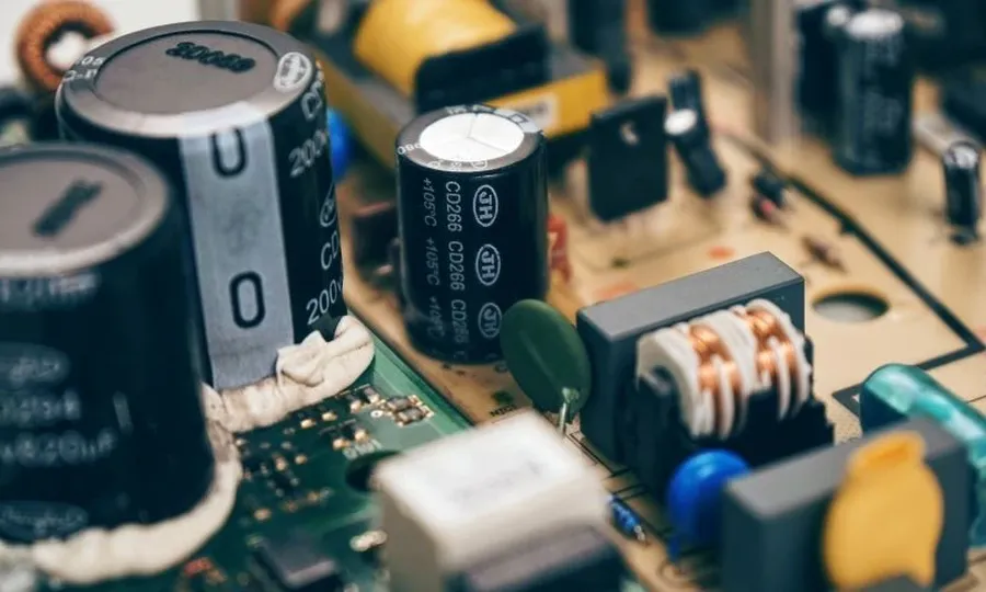
Capacitor specifications, particularly voltage ratings and tolerance, are critical parameters that dictate a capacitor's suitability for a given application. These specifications must be carefully considered to ensure reliable and safe operation within an electronic circuit. The '105' marking only specifies capacitance, and other critical factors must be determined from the capacitor's datasheet.
Voltage rating indicates the maximum voltage a capacitor can safely withstand without risk of dielectric breakdown. Operating a capacitor beyond its rated voltage can lead to damage, failure, and potential safety hazards. The voltage rating is typically specified in volts (V) and can vary greatly depending on the type of capacitor and its intended application. For example, ceramic capacitors marked '105' might range from 16V for small devices to over 100V for some industrial applications. The voltage rating should be chosen by accounting for both the nominal voltage and any voltage transients that are present within the circuit.
Tolerance, on the other hand, defines the allowable deviation of the actual capacitance from its nominal value. It is usually expressed as a percentage of the nominal capacitance. For a '105' capacitor which translates to 1uF, a 10% tolerance will mean the actual capacitance of the component may range from 0.9 uF to 1.1 uF. The acceptable tolerance is determined by the sensitivity of the circuit to changes in capacitance. Tighter tolerances result in more precise performance but are often associated with higher costs. Common capacitor tolerances include ±5%, ±10%, and ±20%, often designated by a letter code found on the capacitor body.
| Parameter | Description | Typical Values for '105' Capacitors | Impact on Performance |
|---|---|---|---|
| Voltage Rating | Maximum safe operating voltage | 16V to 100+V (ceramic); Electrolytic may have lower voltage | Exceeding rating can cause damage or failure |
| Tolerance | Allowable deviation from nominal capacitance | ±5%, ±10%, ±20% | Affects accuracy and circuit stability |
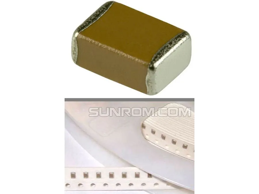
The '105' marking on a capacitor signifies its capacitance value, but it doesn't specify the capacitor's type. While various types can be marked '105,' each exhibits distinct characteristics, including dielectric material, temperature coefficients, and equivalent series resistance (ESR). The most prevalent type found with the '105' marking is the ceramic capacitor.
| Capacitor Type | Typical Characteristics | Common Applications | Advantages | Disadvantages |
|---|---|---|---|---|
| Ceramic Capacitors | Small size, low cost, non-polarized, wide temperature range. Typically X5R, X7R, or NP0 dielectrics. | Bypass, decoupling, filtering in low-power circuits. | Low cost, small form factor, good high frequency performance | Capacitance drift over temperature, voltage dependence, potential for piezoelectric effects. |
| Multilayer Ceramic Capacitors (MLCC) | High capacitance values in small packages, various dielectric types (COG, X7R, Y5V). | Power supply filtering, signal conditioning. | High volumetric efficiency, low ESR, low ESL. | Can be brittle, susceptible to flex cracking, voltage dependence |
| Electrolytic Capacitors (Rarely) | Higher capacitance values, polarized. | Power filtering, energy storage. | High capacitance per volume | Polarized, shorter lifespan, higher ESR and ESL, larger size |
While it's less common, electrolytic capacitors can also bear the '105' marking, however, they typically have larger physical dimensions and are designed for significantly different applications from ceramic capacitors. When dealing with a '105' capacitor, particularly in surface-mount applications, it's almost certain to be a ceramic capacitor, most likely a multilayer ceramic capacitor (MLCC) due to their volumetric efficiency. Understanding the type of capacitor is critical for ensuring it functions correctly within the specified operational parameters.
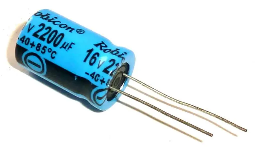
105 capacitors, with their 1µF capacitance, are ubiquitous in electronics due to their versatility in various circuit functions. Their small size and stable characteristics make them ideal for many applications.
They are commonly used in filter circuits for smoothing out voltage ripples in power supplies and for decoupling noise on signal lines. In timing circuits, 105 capacitors can be combined with resistors to form simple RC timing networks for oscillators, delays and pulse generation. Finally, they are used extensively in coupling applications, such as in amplifiers, where they block DC while passing AC signals between stages.
This section addresses common inquiries regarding 105 capacitors, clarifying their markings, values, testing methods, and cost considerations.
Accurately identifying capacitor values is crucial for proper circuit function, and misinterpretations can lead to component damage or circuit malfunction. The 3-digit code, like '105,' is a standardized method, but it's essential to understand the correct conversion to avoid common errors, particularly with unit conversions and voltage ratings.
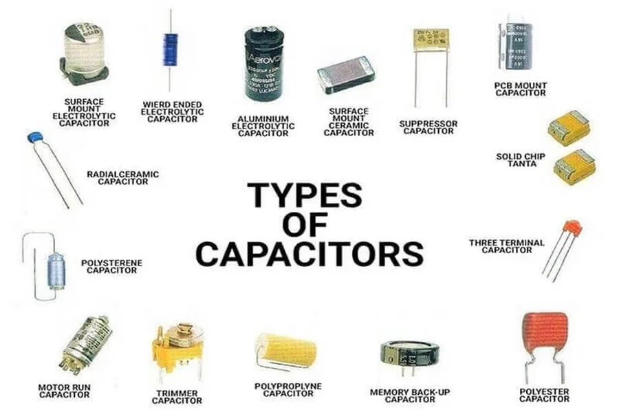
Selecting the appropriate 105 capacitor requires careful consideration of several factors beyond just its capacitance value. Key aspects include the capacitor's working voltage, its operational temperature range, the physical dimensions of its package, and its specific application requirements. A mismatch in any of these parameters can lead to performance issues or even component failure.
| Factor | Description | Impact on 105 Capacitor Selection |
|---|---|---|
| Working Voltage | The maximum voltage the capacitor can safely handle without dielectric breakdown. | Must exceed the highest voltage expected in the application circuit, typically by a safety margin. Under-rating can cause permanent damage. |
| Temperature Range | The operating temperature range within which the capacitor is guaranteed to meet its specifications. | The application's temperature environment must fall within the specified range to ensure stable performance and prevent premature aging or failure. Consider ambient temperature and any heat generated by the capacitor itself. |
| Package Style | The physical size and mounting style of the capacitor (e.g., surface mount, through-hole, radial, axial). | Must match the board layout and mechanical constraints of the application. This includes considerations of lead spacing for through-hole components and pad compatibility for surface mount. |
| Capacitor Type | The material used in the capacitor such as ceramic, electrolytic, or film. | Different capacitor types will have varying properties including tolerance, temperature coefficient, and frequency response. |
| Tolerance | The acceptable variance from the nominal capacitance value, often expressed as a percentage. | Must be considered in applications where precise capacitance is required. A tighter tolerance means more consistent performance across the capacitor's lifetime. |
| Application Requirements | The specific electrical role and operating conditions within the circuit (e.g., filtering, timing, coupling). | Determines the necessary voltage rating, temperature stability, and ESR(Equivalent Series Resistance) characteristics. Each type of capacitor has slightly different behavior under differing frequencies. |
Understanding the '105' marking is crucial for anyone working with electronics. The capacitor 105, usually a 1uF capacitor, plays a vital role in numerous electronic circuits. By understanding its value and characteristics, you can correctly select the right component for your projects and ensure optimal circuit performance. As technology continues to evolve, the importance of understanding these foundational components like the capacitor 105 remains unwavering, highlighting the need for constant learning and adaptation in the field of electronics.

