In the intricate world of electronics, the 0.01uF capacitor might seem like a small component, but it plays a crucial role in many circuits, think of it as the unsung hero of electronics. Just like a tiny bridge in a massive city, it facilitates smooth energy flow within devices. Whether you're a hobbyist or a professional engineer, understanding the nuances of a 0.01uF capacitor is vital. This guide will demystify this essential component, explaining its various types, applications, and selection criteria, all centered around the ubiquitous 0.01uf capacitor.
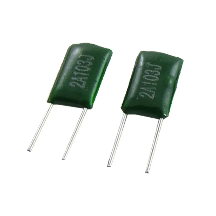
A 0.01uF capacitor is an electronic component that stores electrical energy in an electric field. The value '0.01uF' denotes its capacitance, which is the measure of its ability to store charge, expressed in microfarads (uF). In practical terms, a 0.01uF capacitor is a relatively small capacitor, often used in circuits where small amounts of energy storage or signal filtering are required.
The fundamental unit of capacitance is the farad (F), named after Michael Faraday. One farad is defined as the capacitance of a capacitor that, when charged with one coulomb of electricity, has a potential difference of one volt between its plates. Because the farad is a large unit, it's more common to see capacitance values expressed in microfarads (uF), where 1 uF = 10^-6 F. A 0.01uF capacitor therefore has a capacitance of 0.00000001 farads.
In electronic circuits, 0.01uF capacitors function by accumulating electrical charge on their internal conductive plates, separated by a dielectric material. This ability to store and release electrical energy makes them crucial for a variety of applications, including bypassing, filtering, coupling and timing. In simpler terms, it can block the low-frequency current and pass the high-frequency current. The size of the capacitance determines how much charge is stored and thus its effectiveness in a circuit.
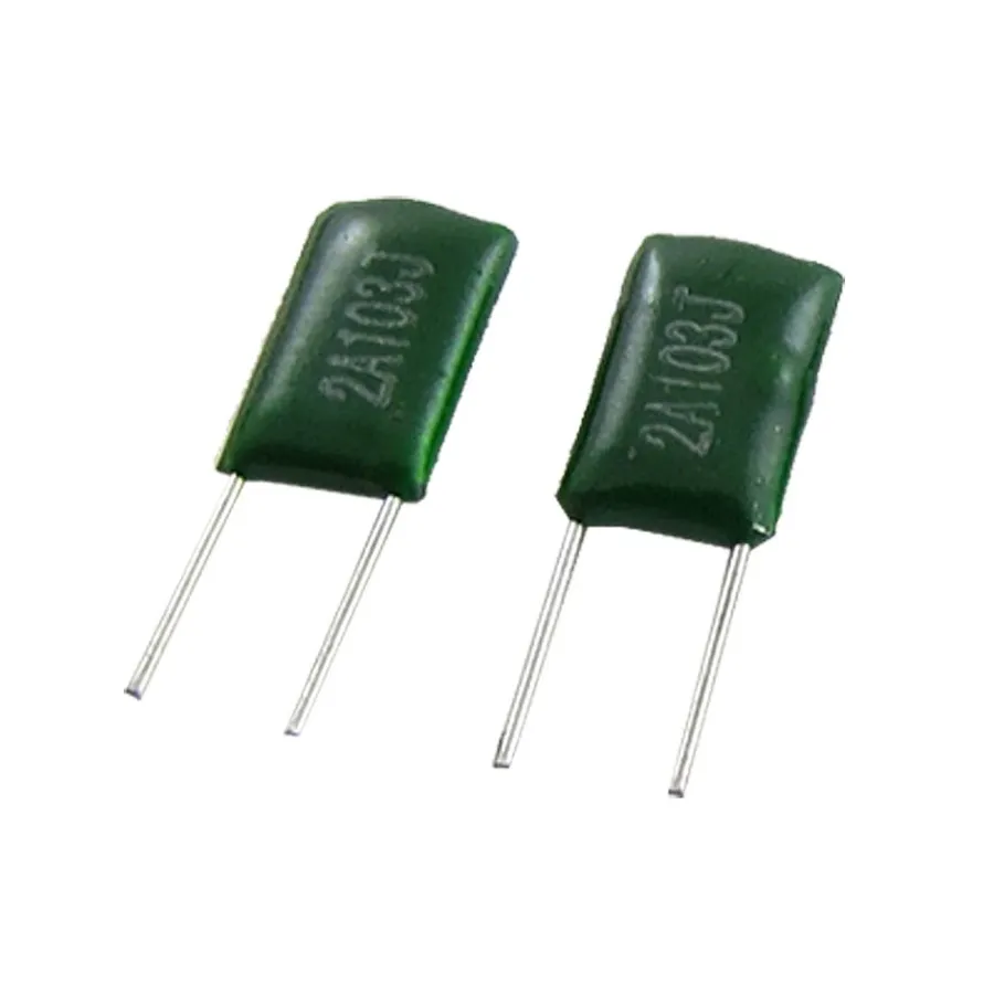
Understanding the key characteristics of a 0.01uF capacitor is crucial for its proper application in electronic circuits. These characteristics dictate how the capacitor will perform under various conditions and within different circuit designs. The most critical parameters include voltage rating, tolerance, and temperature coefficient.
| Characteristic | Description | Typical Values for 0.01uF Capacitor | Importance |
|---|---|---|---|
| Capacitance | The ability of the capacitor to store electrical charge. | 0.01uF (or 10nF) | Fundamental parameter; must match circuit requirements. |
| Voltage Rating | The maximum voltage that can be safely applied across the capacitor. | Varies widely; typically from 16V to thousands of volts | Exceeding can lead to capacitor failure. |
| Tolerance | The allowed deviation of the actual capacitance from the nominal value. | ±5%, ±10%, ±20% | Affects circuit precision; tighter tolerance needed for accurate timing applications |
| Temperature Coefficient | The change in capacitance with temperature. | Varies significantly with material; typically expressed in PPM/°C | Critical for circuits operating over a wide range of temperatures. |
| Dissipation Factor (DF) | Measure of energy loss within the capacitor due to internal resistance. | Typically 0.001-0.02 for ceramic, 0.0001 to 0.01 for film. | Important for high-frequency applications and filtering effectiveness; lower DF means less power loss. |
| Equivalent Series Resistance (ESR) | The total internal resistance of the capacitor; affects performance at higher frequency. | Varies based on capacitor type and construction. | ESR is crucial at high frequencies, especially in decoupling applications. |
| Insulation Resistance | The resistance of the dielectric material to current leakage. | Measured in megaohms, typically very high, can decrease with temperature. | Indicates quality of the dielectric and leakage. |
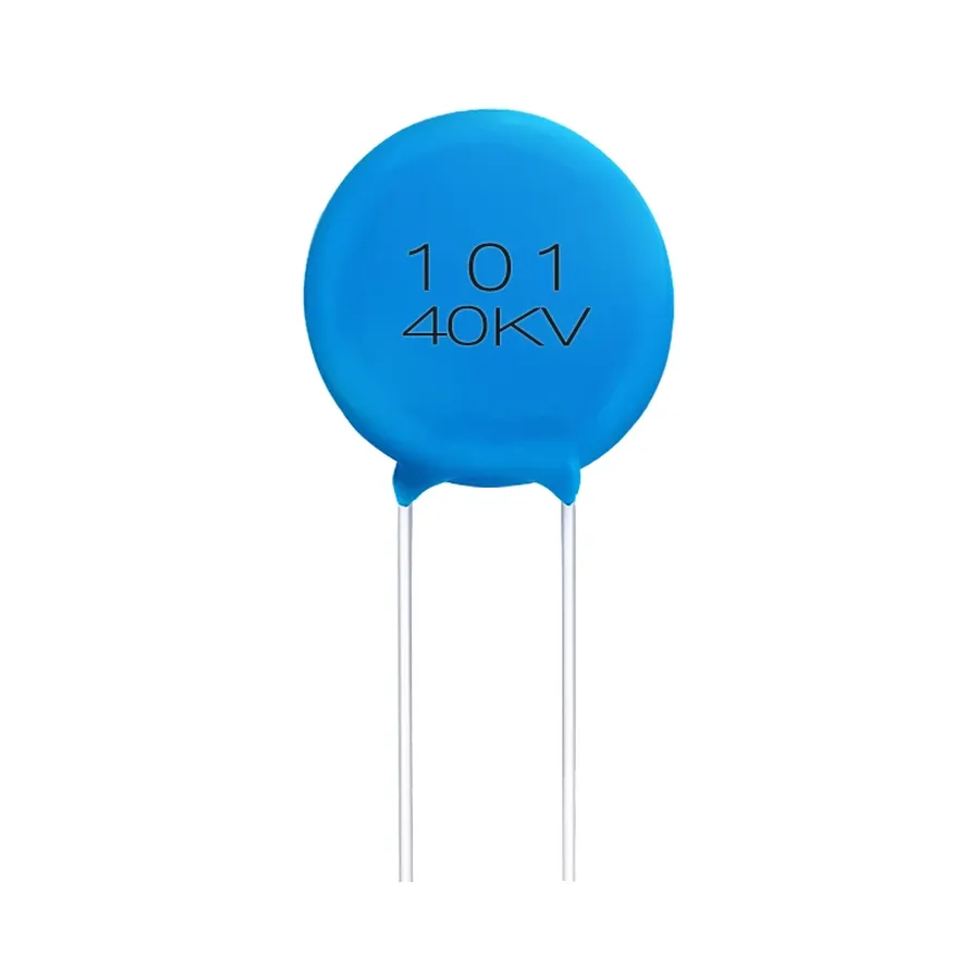
Capacitors with a 0.01uF capacitance value are available in a variety of types, each with its own unique characteristics and ideal applications. The selection of the appropriate type is crucial for optimal circuit performance. Common types include ceramic disc, film (including mylar and polypropylene), and safety capacitors.
| Capacitor Type | Dielectric Material | Typical Applications | Advantages | Disadvantages |
|---|---|---|---|---|
| Ceramic Disc | Ceramic | General purpose, decoupling, bypass | Small size, low cost | Lower precision, temperature sensitive |
| Film (Mylar) | Polyester film | Timing circuits, general purpose | Good temperature stability, higher precision | Larger size, more expensive than ceramic |
| Film (Polypropylene) | Polypropylene film | High frequency circuits, precision timing | Excellent stability and low losses | Larger size, sensitive to high temperatures |
| Safety Capacitors | Various, often ceramic or film | Line filtering, noise suppression | Designed for safety critical applications | Specific safety ratings, may be more expensive |
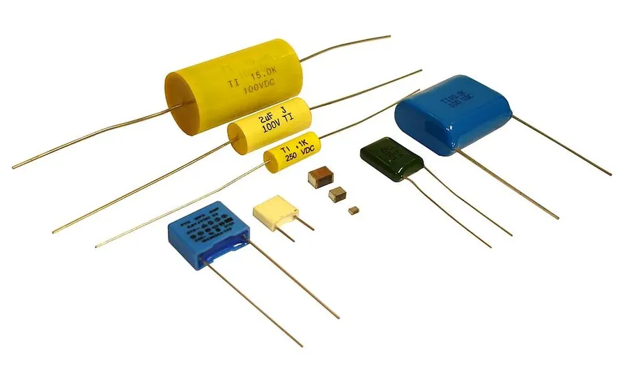
When selecting a 0.01uF capacitor, the choice between ceramic and film types is crucial and depends heavily on the application's specific requirements. Both capacitor types offer distinct advantages and disadvantages that must be carefully considered to optimize circuit performance and reliability.
| Feature | Ceramic Capacitors (0.01uF) | Film Capacitors (0.01uF) |
|---|---|---|
| Capacitance Stability | Can be highly sensitive to temperature and voltage changes, especially Class II and Class III ceramics. | More stable capacitance with respect to temperature and voltage variations. |
| Accuracy & Tolerance | Generally have wider tolerances (e.g., ±10%, ±20%) but can be made to be more accurate at an increased cost. | Typically offer tighter tolerances (e.g., ±1%, ±2%, ±5%). |
| Temperature Coefficient | Varies significantly; can have large capacitance drift over temperature range. | Typically have lower temperature coefficients, ensuring better capacitance stability with varying temperature. |
| Voltage Handling | Available in a wide range of voltage ratings; but higher rated ceramics are physically larger. | Available with different voltage ratings, often with film being the preferred option for high voltage applications |
| Frequency Response | Generally exhibit good high-frequency performance; may have resonance issues. | Better high-frequency performance than ceramics with lower ESR (Equivalent Series Resistance) |
| Size and Form Factor | Typically smaller and more compact; suited for high-density boards. | Generally larger for the same capacitance and voltage ratings. |
| Cost | Generally lower cost, especially for general-purpose applications. | Typically more expensive than ceramic capacitors. |
| Applications | Widely used in decoupling, bypass, and general-purpose circuits where high accuracy and stability are not critical. | Suitable for precision circuits, filters, audio applications, and high-stability requirements. |
| Lifespan | Can degrade over time, especially when exposed to high temperatures or voltage stress. | Generally have longer lifespans and are less susceptible to degradation from temperature and voltage. |
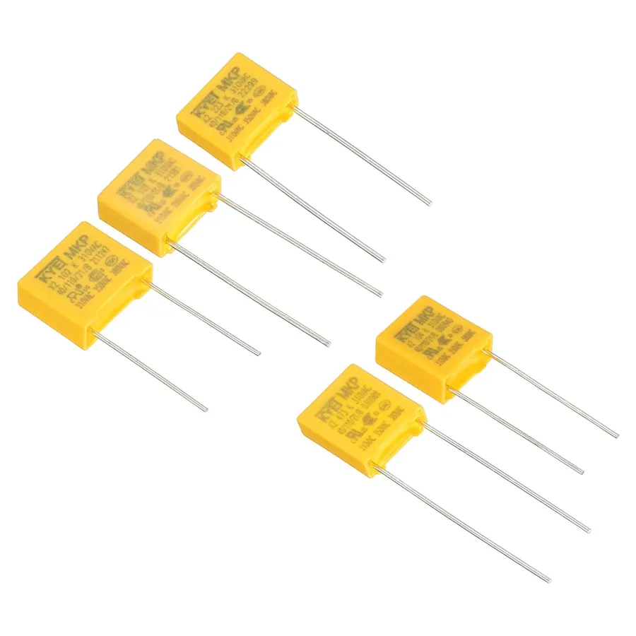
The 0.01uF capacitor, while seemingly small in capacitance, plays a vital role in various electronic circuits. Its primary functions revolve around controlling and shaping electrical signals by storing and releasing energy. This capability allows for its deployment in decoupling, filtering, bypass, and timing applications. The specific application dictates the capacitor's configuration within the circuit.
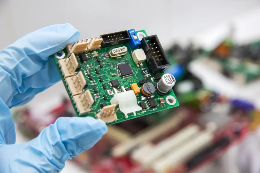
Choosing the appropriate 0.01uF capacitor for a specific application is crucial for ensuring circuit performance and reliability. This selection process involves careful consideration of several key parameters based on the requirements of the circuit where the capacitor will be employed.
The selection process is not merely about matching capacitance; it encompasses ensuring the capacitor can handle the expected electrical stresses and environmental conditions.
| Parameter | Description | Selection Considerations |
|---|---|---|
| Voltage Rating | The maximum voltage the capacitor can withstand without failure. | Must exceed the maximum voltage expected in the circuit. A safety margin is recommended to account for transients or spikes. |
| Temperature Coefficient | How much the capacitance changes with temperature. | Choose a capacitor with a low-temperature coefficient for stable performance across operating temperatures, particularly in environments with temperature fluctuations. |
| Tolerance | The allowable deviation of the actual capacitance from the nominal value. | Select a capacitor with a tolerance appropriate for the application. Tighter tolerances are needed for timing or precision circuits, while less critical applications may tolerate larger variances. |
| Capacitor Type | The dielectric material used in the capacitor (e.g., ceramic, film). | Consider ceramic capacitors for high-frequency applications (e.g. decoupling) and film capacitors where precision and stability are more important (e.g. timing circuits). |
| Size/Package | Physical dimensions and form factor of the capacitor. | Select a size and package compatible with the space available on the circuit board or within the assembly, considering surface mount vs. thru-hole requirements. |
| ESR (Equivalent Series Resistance) | The internal resistance of the capacitor, which affects its performance at high frequencies. | For high-frequency applications, such as decoupling or filtering, select a capacitor with a low ESR to minimize losses and heat generation. |
| Frequency Response | How the capacitor's impedance varies with frequency | Choose the capacitor with impedance appropriate for the frequency range of the signal being handled. For example, ceramic capacitors perform well at high frequencies. |
By evaluating these parameters, engineers can effectively select a 0.01uF capacitor that meets the specific needs of their circuit design and operational context, ensuring performance, longevity and safety.
Identifying a 0.01uF capacitor involves understanding the various marking systems used by manufacturers, which typically include numerical codes, alphanumeric codes, and sometimes color codes. These markings provide crucial information about the capacitor's capacitance value, tolerance, and voltage rating.
Capacitor markings can vary based on the component type (ceramic, film, etc.) and the manufacturer’s practices. However, a fundamental understanding of these codes allows for accurate identification and proper usage.
This section addresses common questions regarding 0.01uF capacitors, providing clear and concise answers to help you understand their usage, characteristics, and alternatives.
Working with 0.01uF capacitors, like any electronic component, requires careful attention to safety. While seemingly small, these capacitors can store electrical energy, and improper handling can lead to component damage, circuit malfunction, or even personal injury. Understanding voltage limits, safe discharge procedures, and general handling practices is crucial.
The 0.01uF capacitor may be a small component, but its role in electronics is significant. From decoupling power supplies to filtering signals, the 0.01uf capacitor is used widely in electronic design. By understanding its characteristics, types, applications, and selection criteria, you're better equipped to use this versatile component effectively and safely, and remember to always verify the correct specs and ratings when working with the 0.01uf capacitor for your projects, ensuring reliable performance and avoiding potential issues.

