Just like how a 1 microfarad capacitor stores a small but crucial amount of electrical energy, our daily lives often depend on equally small yet significant components. From smoothing out power in our smartphones to filtering noise in audio equipment, capacitors play a vital role in modern electronics. This article provides a comprehensive look into the world of 1 microfarad capacitors, exploring their functions, types, and applications, revealing their fundamental importance in engineering and technology. Let's dive in!
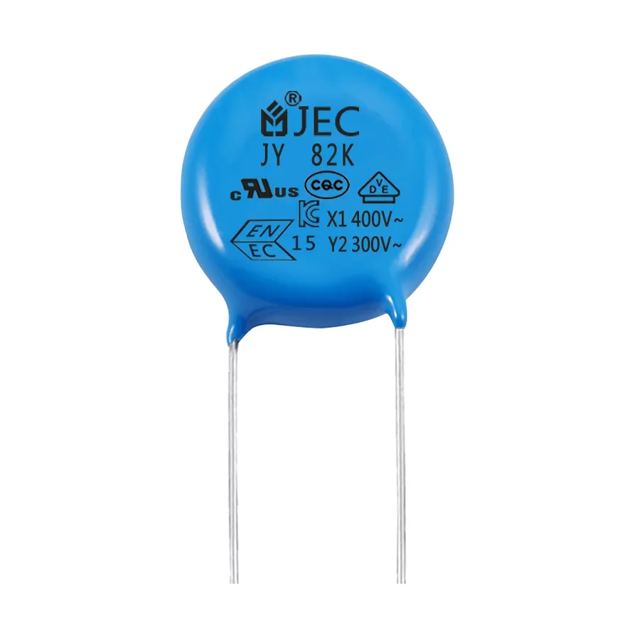
A 1 microfarad (1µF) capacitor is a fundamental electronic component that stores electrical energy in an electric field. The term 'microfarad' represents a unit of capacitance, where one microfarad is one millionth of a farad (1µF = 10⁻⁶ F). Capacitance, measured in farads (F), indicates a capacitor's ability to store charge. Specifically, a 1µF capacitor can store a certain amount of electrical charge for every volt applied across its terminals. This value is a measure of the capacitor's capacity to resist changes in voltage; in essence, it stores charge to maintain a constant voltage level or to filter out fluctuations within an electrical circuit.
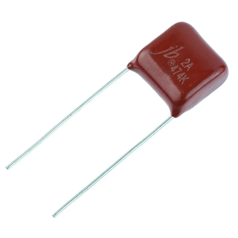
The 1 microfarad (1µF) capacitor is a common component in electronics, available in several types, each with distinct characteristics that make them suitable for different applications. These variations stem from differences in their construction and materials, affecting their performance and behavior in circuits.
| Capacitor Type | Construction | Pros | Cons | Typical Applications | Frequency Suitability |
|---|---|---|---|---|---|
| Ceramic | Multiple layers of ceramic dielectric interleaved with metal electrodes. | Low cost, small size, good temperature stability. | Lower capacitance values, may exhibit piezoelectric effects. | Bypass and decoupling, general-purpose applications. | High |
| Electrolytic | Anode and cathode separated by an electrolyte-soaked paper or film. | High capacitance values, low cost. | Polarized, high ESR, limited frequency response, shorter lifespan, higher leakage current. | Power supply filtering, low-frequency coupling. | Low |
| Tantalum | Tantalum pentoxide dielectric with a porous tantalum anode. | Higher capacitance values, stable over a wide temperature range, reliable. | Polarized, more expensive, can be sensitive to voltage spikes. | High-reliability applications, filtering, decoupling. | Medium |
| Film | Thin plastic film dielectric with metal electrodes. | Low ESR, good stability, wide range of values available, non-polarized. | Larger size, more expensive than ceramic. | Audio circuits, precision timing, high-frequency applications. | High to Medium |
In summary, ceramic capacitors are ideal for high-frequency applications and general use due to their low cost and stability. Electrolytic capacitors are best for applications needing high capacitance at low frequencies, such as power supply smoothing. Tantalum capacitors offer reliability and temperature stability, suitable for critical applications. Film capacitors provide a good balance of performance for applications requiring low loss and good stability.
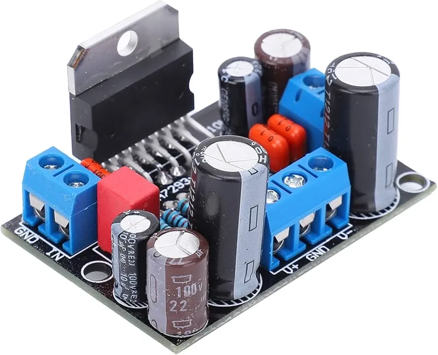
1 microfarad capacitors are fundamental components in a wide array of electronic circuits, performing crucial functions such as power supply filtering, signal decoupling, and timing control. Their versatile nature makes them indispensable in both simple and complex electronic systems.
Below are some common applications of the 1 microfarad capacitor, alongside illustrative case examples:
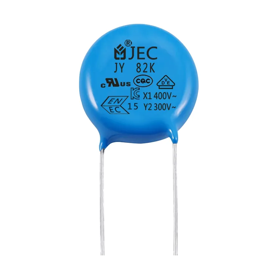
Capacitors, including 1 microfarad (1µF) units, often have markings to indicate their electrical characteristics, including capacitance, voltage rating, and tolerance. These codes can be numerical, alpha-numeric, or color-coded, making it essential to understand these markings to select the appropriate component for a circuit.
Decoding these markings allows for accurate identification of the capacitor's specifications, ensuring proper functionality and preventing potential circuit damage. Manufacturers use various coding schemes, often varying based on capacitor type and physical size.
| Code Type | Description | Example |
|---|---|---|
| Numerical Code | A three-digit code where the first two digits represent the significant figures of the capacitance value and the third digit is the multiplier, indicating the number of zeros to be added in picoFarads(pF). | 105: Represents 10 x 10^5 pF = 1,000,000 pF = 1uF |
| Alpha-Numeric Code | May include letters to denote tolerance and a decimal point or R (for ohm) to mark decimal placement. | 105K: Represents 1uF with 10% tolerance. 105J: Represents 1uF with 5% tolerance. 105M: Represents 1uF with 20% tolerance. For example, 10R = 10 ohms, 1R5 = 1.5 ohms |
| Color Bands | Color bands indicate the capacitance, voltage rating, and tolerance. Refer to the color code chart for specific interpretation. Common in older capacitors. | Similar to resistor color coding but with different color assignments. |
Additionally, some capacitors may include a letter code that specifies the tolerance of the capacitor. For example, J often indicates a 5% tolerance, while K represents 10% and M represents 20% tolerance. It is critical to note that the voltage rating is also very important to check, as exceeding this voltage rating can result in failure of the capacitor.
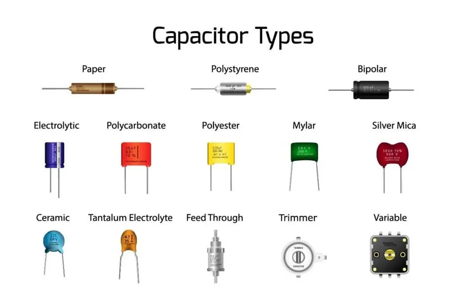
The selection of a capacitor value is a critical aspect of circuit design, directly impacting performance and stability. While a 1 microfarad (µF) capacitor serves various purposes, comparing it with other common values like 0.1µF, 10µF, and 100 nanofarads (nF) reveals distinct application niches. Each value offers unique characteristics that are better suited for certain roles within an electronic circuit.
| Capacitance Value | Typical Applications | Key Characteristics |
|---|---|---|
| 1 µF | General-purpose filtering, decoupling, and timing circuits; audio coupling; motor start capacitors. | Moderate capacitance; balances filtering and size; good for mid-range applications. |
| 0.1 µF (100 nF) | High-frequency decoupling; noise suppression; bypass capacitors; often found close to IC power pins. | Lower capacitance; better for high frequencies; low impedance at higher frequencies; smaller physical size. |
| 10 µF | Bulk decoupling and filtering; power supply smoothing; energy storage; low-frequency filtering. | Higher capacitance; good for low frequencies; can store more charge; larger physical size; slower response to high-frequency signals. |
| 100 nF (0.1µF) | High-frequency bypass; noise filtering; decoupling; often used in digital circuits to stabilize power lines. | Small capacitance; suitable for filtering high frequencies and fast transient signals; fast response time. |
The choice between these values depends heavily on the frequency range, impedance, and energy storage requirements of the application. For example, 0.1 µF capacitors are often used for high-frequency decoupling due to their lower impedance at higher frequencies, effectively suppressing high-frequency noise on power lines. Conversely, 10 µF capacitors, with their higher capacitance, are more effective at smoothing out power supply ripple and providing bulk decoupling for stable voltage levels. A 1 µF capacitor fits in between these, offering a balance of size and performance for a wide variety of uses, making it a versatile component. Lastly, 100nF capacitors, being equivalent to 0.1µF, are often used for high-frequency bypass. Understanding these differences is vital for optimal circuit design and performance.
This section addresses common queries regarding 1 microfarad capacitors, providing clear and concise answers to enhance understanding and dispel any confusion.
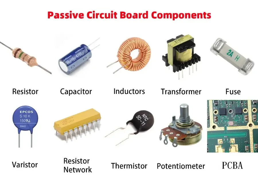
Choosing the correct 1 microfarad capacitor for your project is crucial for optimal circuit performance and reliability. This selection process requires a careful consideration of several key parameters including voltage rating, tolerance, temperature range, and the specific capacitor type.
| Parameter | Consideration | Practical Advice |
|---|---|---|
| Voltage Rating | The maximum voltage the capacitor can withstand without damage. | Select a capacitor with a voltage rating significantly higher than the maximum voltage expected in your circuit. A common rule is to use a capacitor with at least 20% higher voltage rating. |
| Capacitance Tolerance | The allowable deviation from the specified 1 μF capacitance. | For critical timing and filtering applications, choose a capacitor with a tighter tolerance. For less critical applications, a wider tolerance (e.g. ±20%) is sufficient. |
| Temperature Range | The range of temperatures within which the capacitor will operate reliably. | Ensure that the specified temperature range of the capacitor meets or exceeds the operating temperatures expected in your project environment. Consider both operating and storage temperature. For harsh environments, high-temperature stability is vital. |
| Capacitor Type | Ceramic, electrolytic, tantalum, or film capacitors. | Choose the capacitor type based on your application requirements. Ceramic capacitors are good for high-frequency applications. Electrolytic capacitors are suitable for power supplies and high capacitance values, but have a shorter lifespan. Tantalum capacitors are good for high reliability applications, while film capacitors have excellent temperature stability and high voltage handling capability. Note that they come with higher cost. |
| Physical Size | The dimensions of the capacitor. | Consider the available space in your project. Ensure that the selected capacitor physically fits into your circuit board. Surface mount (SMD) components are good for compact designs; through-hole components are good for prototyping. |
| ESR (Equivalent Series Resistance) | A measure of the internal resistance of the capacitor. | For high frequency applications, choose a capacitor with low ESR to minimize signal loss. High ESR is less of a concern for slow or DC applications. |
Testing and troubleshooting a 1 microfarad capacitor is crucial to ensure its proper functionality within an electronic circuit. This section provides a step-by-step approach to assess capacitance, equivalent series resistance (ESR), and leakage current, enabling the identification of faulty components and preventing potential circuit failures.
The 1 microfarad capacitor, seemingly small, plays an indispensable role in the world of electronics. From its ability to filter out noise, to provide timing in circuits, these tiny components are critical to how electronics work. This article has offered a comprehensive view into these components, their types, uses, and how to choose the right one. Whether you are an engineer or a hobbyist, a strong understanding of the 1 microfarad capacitor is important for any electronic project. Just like a 1 microfarad capacitor helps in smoothing out electrical signals, by understanding these concepts will enable smooth project execution. Keep exploring, experimenting and building on your electronics expertise.

