In the realm of electronics, the 10nF capacitor plays a crucial, though often unseen, role. From smoothing power delivery in a sensitive circuit to fine-tuning the frequencies in an audio amplifier, this small component is vital. Like a tiny energy reservoir, the 10nF capacitor, often found in conjunction with other components in circuits, stores and releases electrical charge. In this article, we will dive deep into the intricacies of a 10nF capacitor, its different types, how they work, their specific applications, and why they are indispensable in modern electronics.
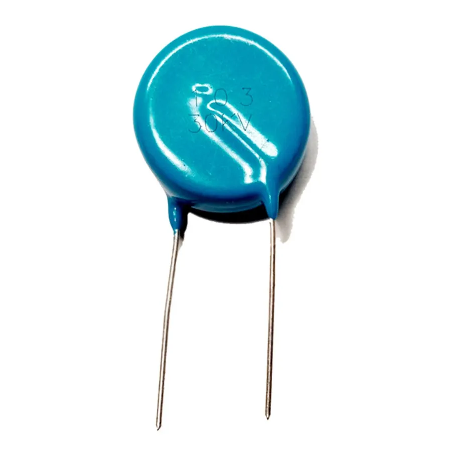
A 10nF capacitor, also known as a 10 nanofarad capacitor, is a fundamental passive electronic component designed to store electrical energy electrostatically within an electric field. The '10nF' specification denotes its capacitance, a measure of its ability to store charge, equivalent to 10 x 10⁻⁹ farads. This capacitance value is crucial in determining how the component will function within an electronic circuit, influencing signal timing, filtering, and energy storage.
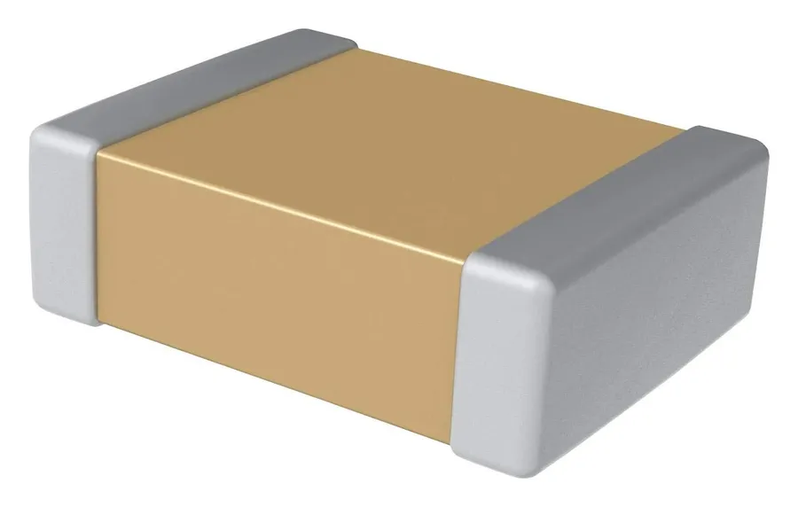
10nF capacitors are manufactured using various dielectric materials and construction techniques, resulting in distinct performance characteristics suitable for diverse applications. Understanding these differences is crucial for selecting the appropriate capacitor for a given circuit.
| Capacitor Type | Dielectric Material | Temperature Coefficient | Voltage Rating | Application Suitability | Typical Cost |
|---|---|---|---|---|---|
| Ceramic | Ceramic (various formulations) | Variable, can be significant for some types | Low to medium | General-purpose, bypass, coupling, filtering | Low |
| MLCC (Multilayer Ceramic Capacitor) | Ceramic (various formulations) | Typically better than single layer ceramic | Low to medium | High-density applications, SMD designs | Low to medium |
| Film | Polyester, Polypropylene | Low, generally more stable | Medium to high | Timing, filtering, precision applications | Medium to high |
Here's a deeper look at each type:
The performance and suitability of a 10nF capacitor in an electronic circuit are determined by its key specifications. These parameters must be carefully considered during design and selection to ensure optimal circuit operation. Understanding these specifications is critical for effective implementation.
| Specification | Description | Typical Values |
|---|---|---|
| Capacitance | The ability of the capacitor to store electrical charge. | 10nF (10 x 10^-9 Farads) |
| Voltage Rating | The maximum voltage that the capacitor can withstand without failing. | Ranges from 50V to 2kV and beyond, depending on the type and application. |
| Tolerance | The acceptable variation in the actual capacitance value from its nominal value. | Typically ±5%, ±10%, or ±20%. Tighter tolerances (e.g., ±1%) are available for precision applications. |
| Temperature Coefficient | The change in capacitance with temperature. | Expressed in parts per million per degree Celsius (ppm/°C). Can be positive, negative or zero. |
| Package Type | The physical form of the capacitor for mounting on a circuit board. | Common types include through-hole (leaded) and surface-mount (SMD). |
Additional specifications may include the Dissipation Factor (DF) (a measure of energy loss) and Equivalent Series Resistance (ESR) (resistance within the component), which are particularly important in high-frequency applications. Selecting a capacitor with adequate specifications ensures reliable performance within the circuit’s operating conditions. Furthermore, the material of the capacitor and its construction also impacts the overall performance.
The 10nF capacitor, a component frequently used in electronic circuits, can be expressed using different units of capacitance. Specifically, a 10nF capacitor is equivalent to 0.01 microfarads (µF) or 10,000 picofarads (pF). These conversions are essential in circuit design to avoid confusion with different unit notations.
| Capacitance Value | Equivalent Value | Conversion Factor |
|---|---|---|
| 10 nF | 0.01 µF | 1 nF = 0.001 µF |
| 10 nF | 10,000 pF | 1 nF = 1,000 pF |
Understanding these conversions is crucial when working with electronic schematics, datasheets, and bills of materials. It minimizes the potential for misinterpretation and ensures accuracy in design and component selection. For instance, a schematic might list a capacitor as 0.01uF while the available part in your lab may be labeled as 10nF, recognizing the equivalent is necessary to ensure correct functionality.
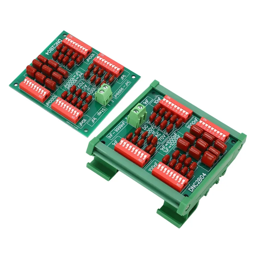
10nF capacitors are versatile components employed across numerous electronic circuits primarily for their ability to store and release electrical energy. Their small capacitance value makes them particularly suitable for high-frequency applications like signal coupling, decoupling, filtering, bypass operations, and timing circuits. A key use is in filtering high-frequency noise from power lines, crucial for preventing interference and ensuring the stable operation of sensitive electronic devices.
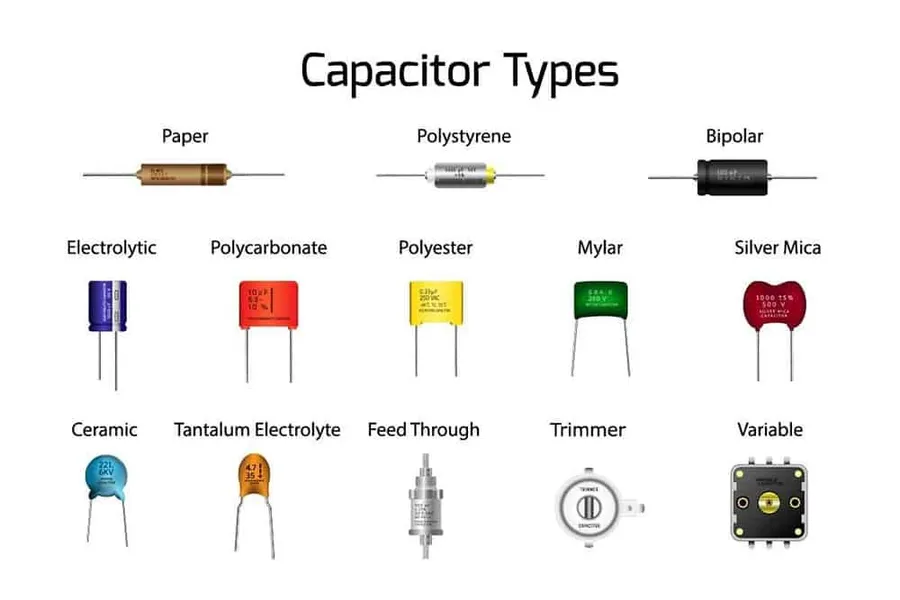
Capacitors, essential components in electronic circuits, often use coded markings to denote their capacitance value. These codes are crucial for identifying and using the correct component in circuit design. For 10nF capacitors, the coding conventions can vary based on the capacitor's type and packaging, with ceramic and surface mount devices (SMD) using distinct methods.
For ceramic capacitors, a common three-digit code is used. In this system, the first two digits represent the significant figures of the capacitance value, and the third digit represents the multiplier, which is a power of 10. The resulting value is given in picofarads (pF). For example, a marking of '103' on a ceramic capacitor indicates a capacitance of 10 x 10³ pF, which converts to 10,000 pF or 10 nF.
| Code | Calculation | Value in pF | Value in nF |
|---|---|---|---|
| 103 | 10 x 10^3 pF | 10,000 pF | 10 nF |
| 223 | 22 x 10^3 pF | 22,000 pF | 22 nF |
| 472 | 47 x 10^2 pF | 4,700 pF | 4.7 nF |
SMD capacitors employ an alphanumeric coding system that can be more complex. These codes are often shorter, since the space for markings is limited. Although there's not a universally followed standard, one approach uses a combination of a letter representing a tolerance, and a two or three digit number representing the capacitance value. These codes may require specific reference guides for decoding and can vary slightly between manufacturers.
It’s important to consult manufacturer datasheets for precise interpretations, especially for SMD components.
This section addresses common inquiries regarding 10nF capacitors, providing clear and concise answers to aid understanding and application. We will cover topics from the basic definition of a 10nF capacitor to the meaning of various markings on capacitors.
When integrating 10nF capacitors into electronic circuits, several best practices should be followed to ensure optimal performance and reliability. These practices focus on voltage considerations, component polarity, capacitance verification, and appropriate packaging.
Selecting the correct 10nF capacitor type is critical for optimal circuit performance. This section provides a comparative analysis of three common types: ceramic, film, and multilayer ceramic capacitors (MLCCs), detailing their attributes, advantages, and limitations to aid in informed decision-making for various applications.
| Attribute | Ceramic Capacitors | Film Capacitors | MLCC Capacitors |
|---|---|---|---|
| Voltage Ratings | Typically low to medium (50V - 1kV) | Medium to high (50V - 2kV+) | Low to medium (50V - 1kV) |
| Temperature Sensitivity | High, capacitance can vary significantly with temperature. | Low, more stable with temperature changes. | Moderate, better than standard ceramics but can still vary. |
| Precision | Lower precision, with larger tolerances. | Higher precision and stability. | Moderate precision, better than standard ceramic capacitors. |
| Application Suitability | General-purpose, bypass, and decoupling. | High-precision timing, audio, and high-voltage applications. | SMD and high-density applications, general-purpose. |
| Cost | Generally low cost | Higher cost compared to ceramic capacitors. | Moderate cost, generally higher than ceramic |
| Size | Compact, available in small packages | Physically larger compared to ceramics and MLCCs. | Very compact, ideal for space-constrained applications |
| Availability | Widely available | Moderately available | Widely available |
Ceramic capacitors are known for their compact size and low cost, making them suitable for general-purpose applications such as decoupling and bypass. However, they exhibit significant capacitance variation with temperature. Film capacitors offer greater precision and stability, making them suitable for timing circuits and high-precision applications but tend to be physically larger and more expensive. MLCCs, a subset of ceramic capacitors, offer better temperature characteristics and are ideal for high-density circuits where space is a constraint. Understanding these tradeoffs will guide engineers in selecting the most appropriate 10nF capacitor for specific design needs.
The 10nF capacitor is a versatile component, integral to numerous electronic circuits and is a component with capacitance of 10 nanofarads. Understanding its characteristics, types, and applications is crucial for anyone working in electronics. Whether you're designing a signal processing unit, or a simple filtering circuit, the 10nF capacitor plays an important role in ensuring proper operation. In a world where more advanced circuitry requires higher precision, these components, like the 10nf capacitor, will remain critical for enabling technological progress.

