Understanding the 1N4004 Diode: A Comprehensive Guide
2025.02.05
Just as a one-way valve controls water flow, the 1N4004 diode is a fundamental electronic component that controls the flow of electricity, allowing current to pass in only one direction. This seemingly simple device is vital in various applications, from simple power supplies to complex circuits, ensuring that your electronics function correctly and safely. This article explores the 1N4004, detailing its function, specifications, and common applications.
What is a 1N4004 Diode?
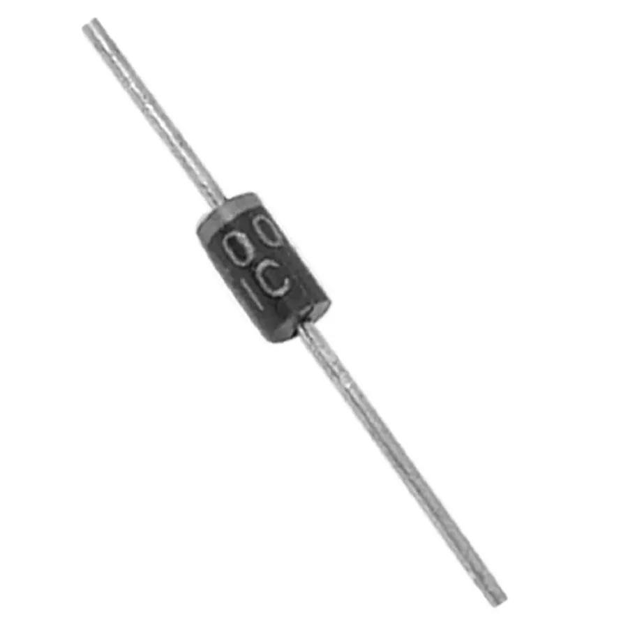
1N4004 Diode
The 1N4004 diode is a silicon-based rectifier diode, primarily used to convert alternating current (AC) into direct current (DC). Its core function stems from its ability to allow current to flow easily in one direction (forward bias) while impeding it in the opposite direction (reverse bias). This behavior is fundamental in electronic circuits for processes like power rectification and signal processing.
Constructed with a P-N junction, the 1N4004 diode forms a depletion region that acts as a barrier to current flow. When a positive voltage is applied to the anode (P-side) and a negative voltage to the cathode (N-side), the depletion region narrows, allowing current to flow. Conversely, when a reverse voltage is applied, the depletion region widens, effectively blocking the current. This unidirectional characteristic makes the 1N4004 a key component in various electronic applications requiring controlled current flow.
1N4004 Diode Specifications and Electrical Characteristics
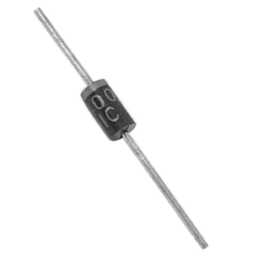
1N4004 Packages
The 1N4004 diode is characterized by several key electrical parameters that dictate its performance in electronic circuits. Understanding these specifications is crucial for selecting the appropriate diode for a given application. This section details the critical characteristics including forward voltage drop, reverse current, peak surge current, and maximum reverse voltage, providing a comprehensive overview using tabular data for clarity.
Parameter
Symbol
Value
Conditions
Unit
Forward Voltage Drop
Vf
1.1
If=1.0A
V
Maximum DC Reverse Voltage
VR
400
V
Peak Repetitive Reverse Voltage
VRRM
400
V
Average Forward Rectified Current
IF(AV)
1.0
A
Peak Forward Surge Current
IFSM
30
for 1 cycle
A
Reverse Current
IR
5
VR=400V
µA
These parameters are essential for the correct operation of the 1N4004 in various applications. For instance, the forward voltage drop indicates the voltage required for the diode to conduct, while the reverse current indicates the leakage when the diode is reverse-biased. The peak surge current is the maximum current the diode can withstand without damage for a very short duration.
1N4004 Pinout and Package Information
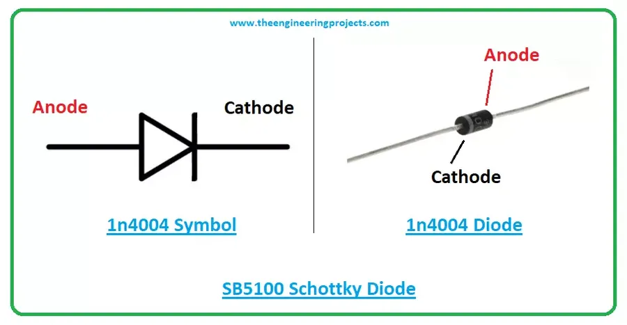
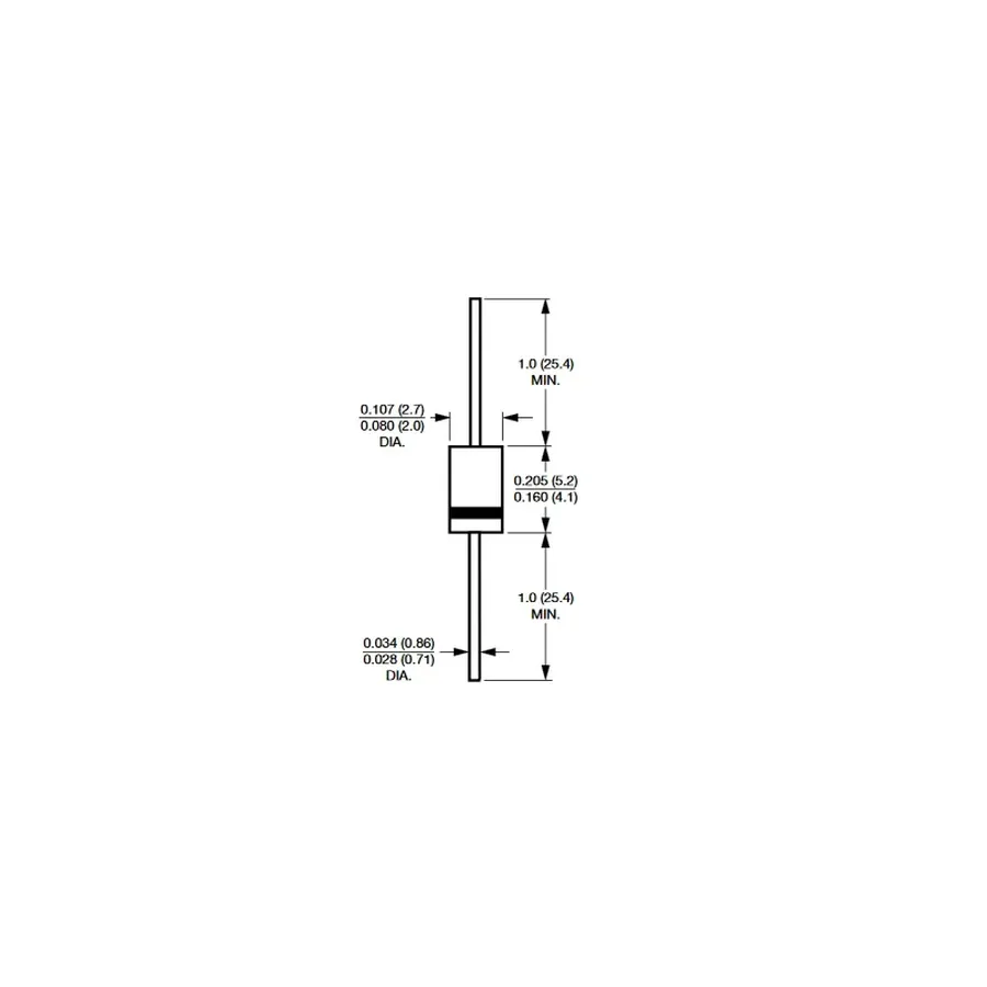
1N4004 Pinout Diagram
The 1N4004 diode, a common rectifier, is characterized by its specific physical structure and packaging. Understanding its pinout and package information is crucial for correct circuit integration and ensuring proper functionality.
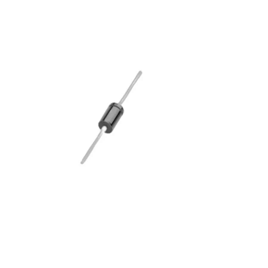
The 1N4004 diode is typically found in a DO-41 (Diode Outline-41) package, which is a through-hole package characterized by its cylindrical shape and axial leads. The package consists of a molded plastic body encasing the silicon diode junction and metal leads extending from each end. These leads facilitate easy soldering into circuit boards or connection with other components.
The 1N4004 is a two-terminal device, consisting of an anode and a cathode. The cathode is typically identified by a band printed on the body of the diode, closer to one of the leads, often white or silver. It's crucial to connect the cathode to the more negative side of the circuit during normal operation.
Feature
Description
Package Type
DO-41 (Diode Outline-41)
Body Material
Molded Plastic (Typically Epoxy)
Lead Configuration
Axial Leads
Terminal Count
2 (Anode and Cathode)
Cathode Identification
Band on the Diode Body
Manufacturers provide detailed drawings and dimensions in the datasheet, which specifies the precise dimensions of the package, including lead length, body diameter, and total length. This allows for accurate placement during PCB design and component assembly.
Applications of the 1N4004 Diode
1N4004 Circuit
The 1N4004 diode, a workhorse in electronics, is primarily employed as a rectifier to convert alternating current (AC) to direct current (DC). Its robust construction and reliable performance make it suitable for a wide array of applications. This section details its common uses, accompanied by example circuits and analysis of their respective advantages and limitations.
Power Supplies In power supply circuits, the 1N4004 diode acts as a crucial component in rectifier circuits, such as bridge rectifiers or half-wave rectifiers. These circuits are essential for converting the AC mains voltage to a usable DC voltage, typically for powering electronic devices. The 1N4004's ability to handle moderate currents and its relatively low forward voltage drop make it well-suited for this application.
Freewheeling Diode In inductive circuits, such as relay drivers or motor controls, the 1N4004 serves as a freewheeling diode. When the inductive load is switched off, the energy stored in the inductor's magnetic field can cause a large voltage spike. The freewheeling diode allows this current to dissipate safely by providing a path for current to flow, thereby protecting other components in the circuit from damage.
Reverse Polarity Protection The 1N4004 diode is frequently used for reverse polarity protection in DC circuits. By placing the diode in series with the power source, it only allows current to flow in the correct direction. If the polarity is reversed, the diode will block the current flow, thereby preventing damage to the sensitive components in the circuit. It is important to note the diode must be rated to handle the expected current to provide robust protection.
Signal Rectification While not its primary use, the 1N4004 diode can also perform signal rectification in circuits where AC signals are present. For example, it could be used in a simple envelope detector circuit to recover the modulating signal from an AM signal. However, the 1N4004 is not optimized for high-frequency applications and other diodes like Schottky diodes are more suitable.
Application
Advantages
Disadvantages
Power Supplies
Effective AC to DC conversion, Moderate current handling
Higher forward voltage drop compared to Schottky diodes
Freewheeling Diode
Protects circuit from voltage spikes, Prevents component damage
Slight delay in circuit response
Reverse Polarity Protection
Simple implementation, Robust protection
Adds a forward voltage drop to the circuit
Signal Rectification
Simple implementation
Not optimized for high-frequency signals
1N4004 Diode Equivalent and Alternatives
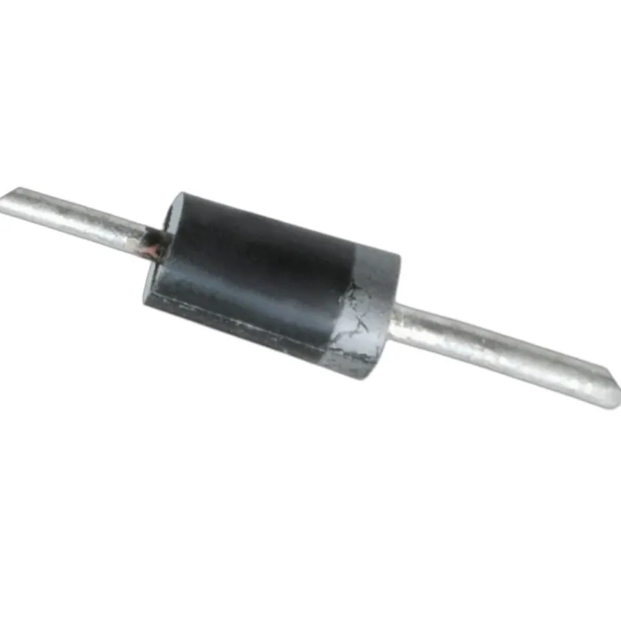
Various Diodes
The 1N4004 diode, while a common rectifier, isn't always the only option. Understanding suitable alternatives and their specifications is crucial for design flexibility and supply chain management. When selecting a replacement for the 1N4004, one must consider key parameters like forward voltage drop, reverse breakdown voltage, and current handling capacity.
Diode Model
Forward Voltage Drop (Typical)
Maximum Reverse Voltage
Maximum Forward Current
Key Differences
1N4001
0.9 V
50 V
1 A
Lower reverse voltage compared to 1N4004
1N4002
0.9 V
100 V
1 A
Higher reverse voltage compared to 1N4001, but lower than 1N4004
1N4004
0.9 V
400 V
1 A
General-purpose rectifier with moderate reverse voltage
1N4007
1.0 V
1000 V
1 A
Highest reverse voltage, suitable for high voltage applications
The 1N4001, 1N4002, and 1N4007 diodes are popular alternatives to the 1N4004. The 1N4001 has a lower reverse voltage rating, while the 1N4007 has a much higher rating. The 1N4002 falls in between. The choice of which diode to use depends on the specific application and voltage requirements. For example, if the circuit will see voltages higher than the 1N4004's reverse voltage limit, then the 1N4007 may be more suitable.
Understanding 1N4004 Diode Datasheet
1N4004 Datasheet Sample
A 1N4004 diode datasheet is a crucial document for any electronics engineer or hobbyist. It provides all the necessary electrical and physical parameters for effectively utilizing the diode in circuit design. Understanding how to interpret this datasheet is essential for selecting the correct diode for your specific application and ensuring reliable performance.
Key parameters to understand in a 1N4004 diode datasheet include:
Maximum Repetitive Reverse Voltage (VRRM) This is the peak voltage that the diode can withstand in the reverse direction without breaking down. The 1N4004 has a VRRM of 400V.
Average Rectified Forward Current (IF(AV)) This refers to the maximum average current the diode can safely carry in the forward direction, typically 1A for the 1N4004. Exceeding this can damage the diode due to thermal overload.
Peak Forward Surge Current (IFSM) This is the maximum non-repetitive forward current the diode can handle for a short duration. The 1N4004 can endure a significant IFSM, which is important when considering transient conditions, such as power-on surges.
Forward Voltage Drop (VF) The voltage drop across the diode when it is conducting forward current. This is typically around 0.7V to 1.1V at the rated forward current, but this value varies with current and temperature and is described within the datasheet using graphs.
Reverse Leakage Current (IR) This is the small amount of current that flows in the reverse direction when the diode is reverse biased. This value is typically in the microampere range and increases with temperature, and is described within the datasheet using graphs.
Operating and Storage Temperature Range The diode’s operational performance and reliability are temperature dependent. Datasheets provide these temperature boundaries within which the diode will function safely, failure to do so will result in unexpected behavior and failure.
Physical Package The dimensions of the package, in this case DO-41, is vital to the construction of PCB's and for understanding the limits of the device.
Beyond these key specifications, datasheets often provide graphs showing how the diode's parameters change with temperature and current. These graphs are important for understanding how the 1N4004 will behave under different conditions, for example, the forward voltage drop is not constant. By consulting the datasheet, engineers can ensure they have the right device for the application.
Frequently Asked Questions About 1N4004 Diodes
This section addresses common queries regarding the 1N4004 diode, clarifying its function, alternatives, and distinctions from other diode types. These questions are compiled to enhance user understanding, drawing from typical user inquiries.
What is the primary function of a 1N4004 diode? The 1N4004 diode is primarily used as a rectifier. Its key function is to allow current to flow in one direction while blocking it in the opposite direction. This makes it ideal for converting alternating current (AC) into direct current (DC) in power supplies and other electronic circuits. The 1N4004’s unidirectional conduction property stems from its internal p-n junction semiconductor structure.
What are some suitable alternatives to the 1N4004 diode? Several diodes can serve as alternatives to the 1N4004, depending on the specific requirements of your application. Common alternatives include the 1N4001, 1N4002, 1N4007 and other members of the 1N400x series. The 1N4007 has a higher peak inverse voltage rating which can make it a more robust substitute in some cases. When substituting any diode, always verify that its electrical characteristics such as voltage, current rating and forward voltage drop are suitable for your circuit.
Is the 1N4004 diode a Zener diode? No, the 1N4004 diode is not a Zener diode. The 1N4004 is a standard rectifier diode designed primarily for forward conduction and reverse blocking. Zener diodes, on the other hand, are designed to operate in reverse bias and conduct once a specific reverse breakdown voltage is reached. They serve the purpose of voltage regulation and overvoltage protection, rather than rectification. These distinct operational modes dictate different designs and applications, making the 1N4004 unsuitable as a Zener diode and vice versa.
What is the difference between a 1N4004 and a 1N4007 diode? The main difference between the 1N4004 and 1N4007 diodes lies in their maximum reverse voltage ratings. The 1N4004 typically has a peak reverse voltage (PRV) rating of 400V, whereas the 1N4007 has a higher PRV rating of 1000V. This means the 1N4007 can withstand higher reverse voltages before breaking down, making it more suitable for applications with potentially higher reverse voltage transients. However, their forward characteristics and current ratings are similar. In typical applications, the 1N4007 is often used as a more robust replacement for lower voltage parts, such as the 1N4004.
What should I consider when choosing a diode as a replacement for a 1N4004? When selecting a substitute for the 1N4004, you must carefully match the electrical specifications to the circuit's requirements. Key factors to consider include: the maximum forward current, peak inverse voltage, forward voltage drop, operating temperature range, and the physical package type. In cases where a higher voltage rating is needed, the 1N4007 is a direct substitute. Ensuring that the replacement diode meets or exceeds all the requirements of the 1N4004 in your circuit is critical for maintaining the circuit's performance and avoiding potential failure. Always consult datasheets to make accurate comparisons.
Can a 1N4004 diode be used in high-frequency circuits? While the 1N4004 diode can operate up to certain frequencies, it is generally not optimized for high-frequency applications. Its relatively slow reverse recovery time means that it may not switch off quickly enough at higher frequencies, which could cause energy losses and reduce efficiency. For high-frequency circuits, it's preferable to use diodes specifically designed for fast switching, such as Schottky diodes or fast recovery diodes. These have much shorter reverse recovery times and are more efficient in high-frequency environments.
Practical Tips for Using the 1N4004 Diode
1N4004 on PCB
The 1N4004 diode, while robust for its intended applications, requires careful handling to ensure optimal performance and longevity. This section provides practical advice on how to avoid common pitfalls associated with its use, focusing on thermal management, overcurrent protection, and proper integration techniques.
Thermal Management Excessive heat can degrade a diode's performance and shorten its lifespan. When soldering, use a temperature-controlled iron and apply heat for the shortest duration possible to prevent heat transfer to the diode's body. If high power dissipation is expected, consider using a heat sink or other thermal management techniques.
Overcurrent Protection The 1N4004 has a specified peak surge current rating, typically around 30A for a short duration. Exceeding this rating, even momentarily, can cause irreversible damage or failure. Use appropriate current-limiting devices, such as fuses or resistors, to ensure that the diode operates within its safe operating limits. For continuous current applications, make sure the average forward current does not exceed its maximum rated value.
Soldering Best Practices Use a fine-tipped soldering iron and lead-based solder for best results. Avoid prolonged heating of the diode leads. Use a heatsink clip on the lead between the diode and solder point for better thermal control during soldering. Always allow the soldered joints to cool down naturally, avoid active cooling which may introduce thermal stress.
Circuit Integration When integrating the 1N4004 into a circuit, ensure correct polarity. The cathode (banded end) must be connected to the lower potential side for proper operation. Incorrect polarity can cause reverse breakdown and damage the diode or other components. Double-check all connections before applying power.
Storage Conditions Store 1N4004 diodes in a dry, static-safe environment. Avoid storing in areas with extreme temperatures or humidity, as this can lead to oxidation and degradation of leads and the semiconductor materials. Use antistatic bags or containers for protection.
The 1N4004 diode, while seemingly simple, is a crucial component in electronics. Its reliability in power rectification, combined with its wide availability, make it a staple in circuit design. Knowing how it works and how to use it, along with its limitations, empowers you to build robust, reliable circuits. As you continue your journey in electronics, remember the 1N4004, a tiny guardian of current flow.