Have you ever stopped to think about the tiny components that make our electronics tick? One such unsung hero is the resistor, and the 250 ohm resistor is a particularly versatile example. From controlling current flow in industrial sensors to precision measurement in communication devices, this small component plays a critical role. This article will dive into the applications, selection criteria, and key factors to consider when working with a 250 ohm resistor, opening your eyes to the world of practical electronics.
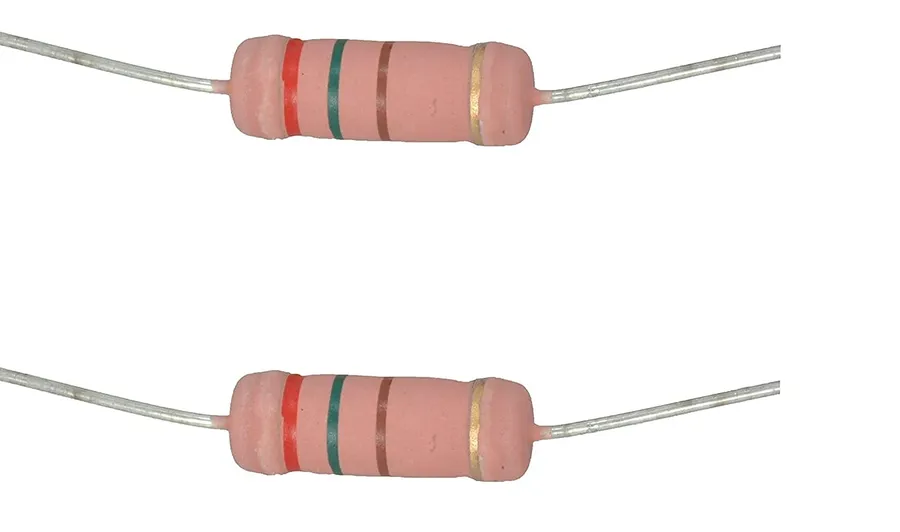
A 250 ohm resistor is a fundamental passive electronic component designed to impede the flow of electrical current by a precise amount, specifically offering a resistance of 250 ohms. This defined resistance is crucial for controlling current within electrical circuits, making it a ubiquitous element in electronic design.
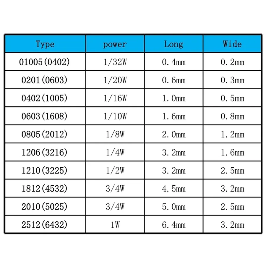
Understanding the specifications of a 250 ohm resistor is crucial for its proper application in electronic circuits. These specifications, including power rating, tolerance, and physical size, dictate how the resistor will perform under different operating conditions and within various circuit designs. Selecting the correct resistor ensures circuit stability and prevents component failure.
| Specification | Description | Impact on Selection |
|---|---|---|
| Power Rating (Watts) | The maximum amount of power a resistor can dissipate without damage, commonly seen in ratings such as 1/4W, 1/2W, 1W, 2W, 5W, and higher. For example, a 1/4W resistor is suitable for low-power signal applications. | Determines the resistor's capacity to handle heat generated by current flow. A higher power rating is needed if significant power is expected to pass through the resistor, preventing overheating and damage. |
| Tolerance (%) | The acceptable deviation from the nominal 250 ohm resistance value. Common tolerances include 1%, 5%, and 10%. For precision applications, a 1% tolerance is typically desired, meaning a 250 ohm resistor with 1% tolerance will have its actual resistance value between 247.5 ohm and 252.5 ohm. | Impacts the accuracy of the circuit. Lower tolerance resistors offer more consistent and predictable performance, crucial for circuits requiring tight precision. |
| Physical Size | The physical dimensions of the resistor, which can vary significantly based on the power rating and type (e.g., through-hole or surface mount). Sizes range from small surface mount components (e.g., 0402, 0603) to larger through-hole resistors. Larger physical size usually correlates with higher power rating capabilities. | Determines suitability for different circuit layouts and mounting methods. Smaller sizes are advantageous for compact PCBs, while larger sizes often imply a higher power handling capacity. |
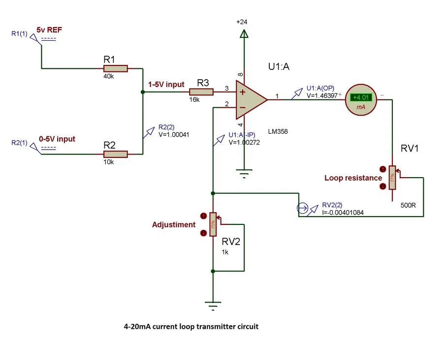
In industrial automation and instrumentation, the 4-20mA current loop is a ubiquitous standard for transmitting sensor data. A critical component in these systems is the 250 ohm resistor, which serves to convert the 4-20mA current signal into a 1-5V voltage signal. This conversion is essential for interfacing with analog input modules of programmable logic controllers (PLCs) and other data acquisition systems, which typically read voltages rather than currents.
The principle behind this conversion lies in Ohm's Law (V=IR), where voltage (V) is the product of current (I) and resistance (R). When a 4-20mA current flows through a precision 250 ohm resistor, it produces a voltage drop ranging from 1V to 5V. Specifically, a 4mA current results in 1V (0.004A * 250Ω = 1V), while a 20mA current yields 5V (0.020A * 250Ω = 5V), forming a linear relationship between the measured current and the resulting voltage.
| Current (mA) | Resistance (Ω) | Voltage (V) |
|---|---|---|
| 4 | 250 | 1 |
| 8 | 250 | 2 |
| 12 | 250 | 3 |
| 16 | 250 | 4 |
| 20 | 250 | 5 |
The choice of a 250 ohm resistor is not arbitrary; it is standardized to provide a convenient voltage range (1-5V) that is easily handled by common industrial controllers. This standardisation simplifies the design and interoperability of industrial systems, ensuring that different instruments and control devices can communicate effectively. The precision and stability of the 250 ohm resistor are crucial for accurate measurements. Any variation in resistance could introduce errors in signal interpretation, which is why low tolerance resistors are essential for these applications.
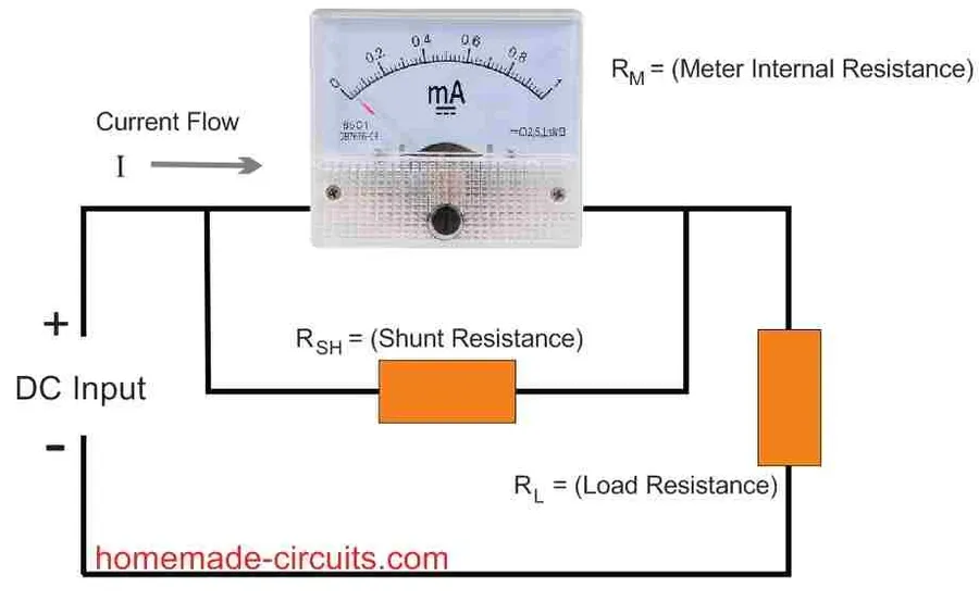
A 250 ohm shunt resistor is strategically placed in a circuit to create a voltage drop that is proportional to the current flowing through it. This voltage drop serves as a measurable signal, allowing for current monitoring without interrupting the main circuit path. Specifically, the 250 ohm resistor's defined resistance makes it a crucial component in industrial applications where accurate signal conversion and monitoring are essential.
Shunt resistors are essential for several reasons. Firstly, they allow the measurement of high currents that would otherwise be difficult or dangerous to measure directly with most standard voltmeters or ammeters. Secondly, they provide a predictable and repeatable way to convert a current signal into a voltage signal, which is often more convenient for subsequent processing or analysis. The 250 ohm resistor, in particular, is widely utilized in 4-20mA current loops to provide this conversion, establishing a direct correlation between measured voltage and loop current.
Consider a scenario where a 4-20mA current loop is used to transmit a sensor measurement. By placing a 250 ohm shunt resistor in this loop, the 4-20mA current range is converted to a 1-5V voltage range (V=IR). This is because V = 0.004 * 250 = 1V and V = 0.020 * 250 = 5V. This linear relationship enables signal conditioning and processing in downstream circuits, forming the basis for many industrial control systems. The accuracy of the 250 ohm resistor in the shunt application determines the accuracy of the converted signal.

Choosing the correct 250 ohm resistor is crucial for optimal circuit performance and reliability. This selection process involves considering several key factors, including power rating, tolerance, mounting style, and environmental conditions, ensuring the resistor meets the specific demands of its application.
| Factor | Description | Impact on Selection |
|---|---|---|
| Power Rating | The maximum power the resistor can dissipate without damage (e.g., 1/4W, 1/2W, 1W, 5W). | Select a rating significantly above the expected power dissipation in the circuit to prevent overheating and failure. Calculate power using P = I²R or P=V²/R. |
| Tolerance | The allowable deviation from the nominal resistance value (e.g., ±1%, ±5%, ±10%). | Choose tighter tolerances for precision applications and looser tolerances for less critical circuits. Precision instrumentation may require ±0.1% or even tighter tolerances. |
| Mounting Type | Through-hole (leaded) or surface mount (SMD). | Select based on circuit board design. Through-hole is often used for prototyping and lower volume manufacturing; SMDs are more common in high-volume production. |
| Temperature Coefficient | The change in resistance per degree Celsius change in temperature. (PPM/°C) | Important for applications where temperature changes can significantly impact circuit performance. Choose resistors with low temperature coefficients to minimize drift. |
| Environmental Factors | Operating temperature range, humidity, and exposure to corrosive substances. | Select resistors with appropriate environmental ratings and consider using conformal coatings to protect against humidity or chemicals. High-temperature applications may require specialized resistors rated for higher temperature. |
| Application-Specific Requirements | Specific needs dictated by the circuit or equipment (e.g., pulse handling, high-frequency operation, non-inductive) | Different applications require different types of resistors. High-frequency applications may require low-inductance resistors. Applications with frequent high current pulses might require higher surge current capacity. |
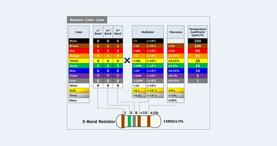
The color code system is a standardized method for identifying the resistance value of a resistor. Each color corresponds to a numerical value, and by reading the color bands on a resistor, you can determine its resistance, tolerance, and sometimes its temperature coefficient. This method is crucial for quick identification in electronic circuits and reduces the need for direct measurement in many cases. For a 250 ohm resistor, specific color bands are used to represent this value.
| Band | Color | 1st Digit | 2nd Digit | Multiplier | Tolerance |
|---|---|---|---|---|---|
| 1st | Red | 2 | - | - | - |
| 2nd | Green | 5 | - | - | - |
| 3rd | Black | - | - | x1 | - |
| 4th | Black | - | - | - | ±10% |
For a standard 4-band 250 ohm resistor, the color bands are typically: 1. **First Band:** Red (represents the digit 2) 2. **Second Band:** Green (represents the digit 5) 3. **Third Band:** Black (represents a multiplier of x1) 4. **Fourth Band:** Black (represents a tolerance of ±10%) Thus, the color sequence Red, Green, Black, Black translates to 25 x 1 = 25 ohm ±10%, Please note, that the 250 ohm resistor will have the forth band, which is the tolerance band, of gold or silver. This example assumes a 10% tolerance for simplicity. It is also very important to understand the role of 5 band resistors.
A 250 ohm resistor frequently functions as a load resistor, particularly within industrial communication systems like those employing the Highway Addressable Remote Transducer (HART) protocol. In these applications, the resistor serves a critical role in facilitating signal interpretation and ensuring proper device operation by providing a known resistance for current-to-voltage conversion.
Specifically within HART communication, the 250 ohm resistor is crucial for creating a voltage drop that is proportional to the current flowing in the loop. This voltage drop is then monitored by the HART communicator, allowing it to accurately decode the digital data superimposed on the 4-20mA current signal. This ensures reliable bidirectional communication with field devices.
The selection of a 250 ohm resistor for load applications must consider its power rating, tolerance, and stability. These characteristics ensure accurate voltage measurements and signal integrity. Typically, a precision resistor with a low temperature coefficient is preferred to minimize the impact of environmental variations on the accuracy of measurement.
| Characteristic | Importance in Load Applications |
|---|---|
| Resistance | Must be precisely 250 ohms to ensure correct voltage drop for signal conversion. |
| Power Rating | Must be sufficient to dissipate heat generated by the current flowing through it, preventing overheating and ensuring stability. |
| Tolerance | Lower tolerance ensures accurate signal representation and prevents measurement errors. |
| Stability | Resistance should remain stable over time and under varying operating conditions to maintain measurement accuracy. |
This section addresses common queries about 250 ohm resistors, providing clear, concise answers to help you understand their applications and selection process.
The 250 ohm resistor, while seemingly simple, plays a crucial role in countless electronic applications. Whether it's enabling precise measurements in industrial settings or ensuring stable current flow in consumer devices, understanding its function and specifications is key for any electronics enthusiast or professional. This article has provided an overview of the 250 ohm resistor, highlighting its diverse applications and practical considerations for selection, ensuring you can confidently select and implement it in your next electronics project. Remember the importance of selecting the correct power rating and tolerance and consider the context of your circuit when using the humble 250 ohm resistor.

