In the intricate world of electronics, the humble 10uF capacitor plays a crucial role, much like a tiny reservoir that stores and releases energy. From smoothing out voltage fluctuations in power supplies to enabling delicate filtering in audio circuits, this seemingly small component is vital. This article will delve into the characteristics of the 10uF capacitor, examining its diverse types, applications, and selection criteria, empowering you to make informed decisions in your electronic projects.
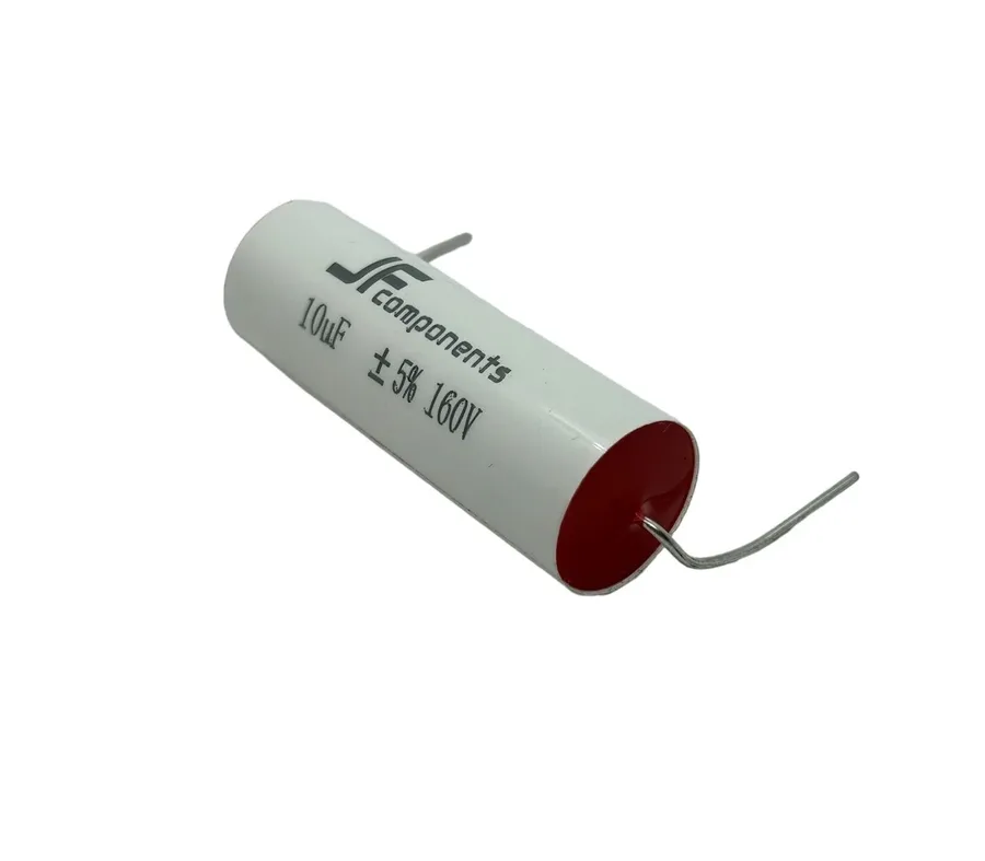
A 10uF capacitor is a fundamental electronic component characterized by its ability to store 10 microfarads (10 x 10⁻⁶ farads) of electrical charge. This capacity to store charge makes it a critical element in various circuits, performing functions such as filtering, energy storage, and timing, distinct from resistors that impede current flow and inductors which store energy in a magnetic field. The '10uF' designation refers specifically to its capacitance, a measure of how much charge it can store at a given voltage.
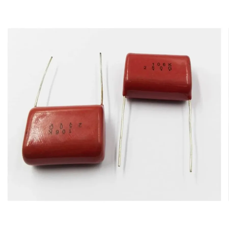
10uF capacitors, while sharing a common capacitance value, come in various types, each with distinct characteristics, advantages, and suitable applications. The primary types are Electrolytic, Ceramic, and Film capacitors. Understanding their differences is crucial for selecting the appropriate component for a given electronic circuit. This section details these key distinctions, providing a comprehensive guide for design and application.
| Feature | Electrolytic | Ceramic | Film |
|---|---|---|---|
| Structure | Uses an electrolyte (liquid or solid) as one electrode, separated by a thin oxide layer. | Uses a ceramic dielectric material, typically in a multi-layered structure. | Uses a thin plastic film as the dielectric material. |
| Capacitance Range | Generally high, suitable for large charge storage. | Typically low to medium, good for high-frequency applications. | Medium range, often used in precision circuits. |
| Voltage Ratings | Moderate to high, typically up to several hundred volts. | Lower, generally ranging from a few volts to several hundred. | Moderate to very high, suitable for high-voltage applications. |
| Advantages | High capacitance per volume, cost-effective for bulk energy storage. | Low cost, small size, low ESR, excellent high-frequency performance. | High precision, excellent temperature stability, low loss, good long-term reliability. |
| Disadvantages | Polarized (must be installed correctly), shorter lifespan, higher ESR, sensitive to temperature. | Capacitance varies with voltage, temperature, and time. Prone to cracking, may have microphonic effects. | Larger size, higher cost compared to ceramics, more sensitive to humidity. |
| Applications | Power supply filtering, decoupling, energy storage, smoothing. | High-frequency decoupling, signal filtering, bypass capacitors. | Precision timing circuits, audio coupling, analog signal processing. |
| Typical Frequencies | Low to moderate frequencies. | High frequencies and RF applications. | Low to high frequencies, depending on film material. |
| ESR (Equivalent Series Resistance) | Higher ESR compared to ceramic and film capacitors. | Very low ESR. | Low ESR. |
The voltage rating and tolerance of a 10uF capacitor are critical parameters that directly influence its safe and effective operation within an electronic circuit. Choosing a capacitor with an inappropriate voltage rating or tolerance can lead to component failure, circuit malfunction, or even safety hazards.
Voltage Rating: This specifies the maximum DC voltage that a capacitor can withstand continuously without risking damage or failure. Exceeding this rating can degrade the capacitor's dielectric material, leading to reduced capacitance, increased leakage current, or catastrophic failure. The rated voltage is typically marked on the capacitor body or its packaging. It's crucial to choose a capacitor with a voltage rating that is higher than the maximum voltage expected in the circuit, providing a safety margin. A common rule of thumb is to choose a capacitor with a voltage rating at least 20% higher than the maximum expected voltage.
Tolerance: This parameter indicates the acceptable deviation of the actual capacitance value from the nominal value (10uF in this case). Tolerance is usually expressed as a percentage (e.g., ±5%, ±10%, ±20%) or a letter code. For example, a 10uF capacitor with a ±10% tolerance could have an actual capacitance value ranging from 9uF to 11uF. The impact of tolerance on circuit performance depends on the application. In timing circuits or high-precision applications, tight tolerance is critical for predictable operation. For less sensitive applications, such as power supply decoupling, wider tolerances may be acceptable. Capacitors with tighter tolerances are generally more expensive.
Consequences of Improper Selection: Using a capacitor with a voltage rating below the circuit's requirements can result in dielectric breakdown, causing the capacitor to short circuit, which may result in damage to the capacitor itself and other circuit components. Also, using a capacitor with incorrect tolerance can lead to unpredictable circuit behavior and potentially cause system malfunction. Therefore, it is important to consider both voltage rating and tolerance when selecting a 10uF capacitor.
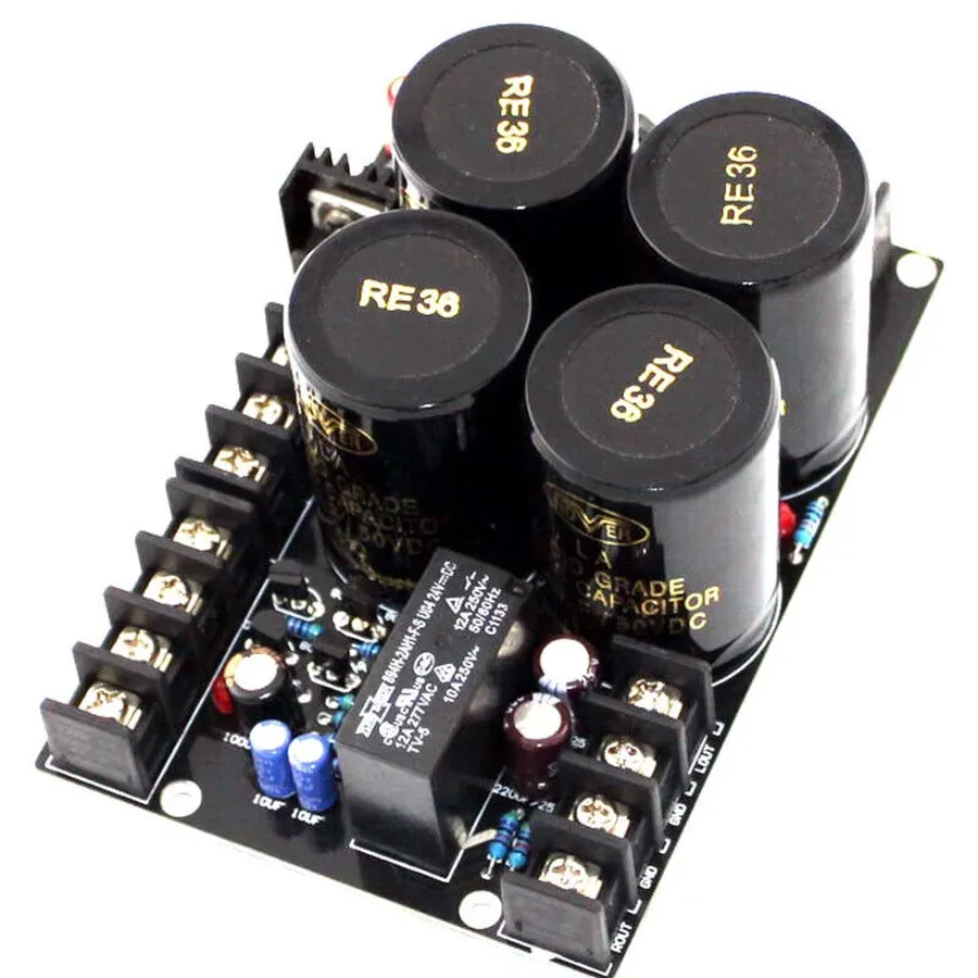
10uF capacitors are integral components in numerous electronic applications, leveraging their ability to store and release electrical energy. They are particularly well-suited for tasks such as power supply filtering, audio signal coupling, timing circuits, and motor starting, each of which benefits from their specific electrical characteristics. Their role in smoothing voltage fluctuations, passing AC signals while blocking DC, establishing precise timing intervals, and providing starting torque for motors highlights their versatility in electronics design.
Below is a breakdown of common applications:
Selecting the correct 10uF capacitor is critical for optimal circuit performance and reliability. The ideal choice depends on a variety of factors, including the specific application, voltage requirements, operating temperature range, physical size constraints, and desired performance characteristics. Ignoring these factors can lead to component failure, circuit malfunction, or reduced lifespan of the electronic device.
Here's a breakdown of key considerations:
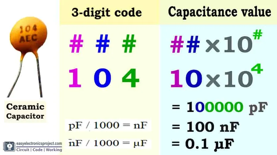
Deciphering the codes and markings on a 10uF capacitor is crucial for proper component selection and circuit functionality. These markings, though often small and seemingly cryptic, convey essential information about the capacitor's specifications, including its capacitance, voltage rating, tolerance, and sometimes even its temperature coefficient. This guide will explain how to interpret these markings, providing clarity and ensuring you choose the correct 10uF capacitor for your application.
Capacitor markings can vary depending on the capacitor type and manufacturer. Here's a breakdown of the common codes and markings you may encounter:
Sometimes, capacitor markings use a numerical coding system, especially for ceramic capacitors. For example, '106' may indicate 10 x 10^6 pF which is equivalent to 10uF. Always refer to the manufacturer's datasheet when dealing with unfamiliar codes.
When markings are unclear, it is crucial to exercise caution. If the markings are incomplete or faded, it is advisable to: 1. Check the circuit diagram or documentation to verify the correct capacitor specifications, if available. 2. Try to identify the manufacturer's logo or a unique marking and search the manufacturer’s database or use online capacitor marking decoders. 3. If uncertain, err on the side of caution and use a capacitor with a higher voltage rating than expected. 4. In cases of ambiguity, it is always best practice to use a multimeter and measure the actual capacitance. If the capacitance is not within tolerance, it indicates a faulty capacitor.
This section addresses common queries regarding 10uF capacitors, providing both technical insights and practical advice to enhance understanding and application.
A comparative analysis of 10uF capacitors across different types—Electrolytic, Ceramic, and Film—is essential for selecting the optimal component for specific applications. This section details the key specifications and typical use cases, providing a practical guide for engineers and hobbyists.
| Feature | Electrolytic 10uF | Ceramic 10uF | Film 10uF |
|---|---|---|---|
| Voltage Range | Low to Medium (e.g., 6.3V to 450V) | Low to Medium (e.g., 6.3V to 100V) | Medium to High (e.g., 50V to 1000V) |
| Temperature Range | -40°C to +105°C (typically); High temp options avail | -55°C to +125°C (Typically) | -55°C to +150°C |
| Frequency Response | Lower, Suitable for DC & low-frequency applications | Excellent, Suitable for high-frequency applications | Good, Suitable for audio and other medium-frequency applications |
| Size | Generally larger | Small, available in SMD packages | Moderate to larger, depending on voltage rating |
| Price | Cost-effective | Low to moderate cost | More expensive |
| Best Use Cases | Power supply filtering, decoupling, smoothing, and bulk storage | High-frequency circuits, decoupling in digital circuits, bypass | Audio circuits, precision timing, high-reliability applications |
| Polarity | Polarized, requires correct orientation in circuit | Non-Polarized | Non-Polarized |
| ESR (Equivalent Series Resistance) | Higher ESR | Lower ESR | Lower ESR, very stable |
| Tolerance | Higher tolerance | Lower tolerance | Typically tighter tolerance |
The 10uF capacitor, a seemingly simple component, is a cornerstone of modern electronics. Whether it's the stability of a power supply, the clarity of an audio signal, or the smooth operation of a motor, the 10uF capacitor plays a critical role. By understanding its diverse types, key parameters like voltage and tolerance, and practical applications, you're better equipped to select and use this essential component effectively. As technology advances, the 10uF capacitor will continue to be a fundamental element in innovative electronic designs. This understanding will lead to improved design, higher performance and more reliable electronics.

