Imagine building electronic circuits without the hassle of soldering – that's the magic of a solderless breadboard! This tool, a staple in electronics labs and hobbyist workshops, allows for quick and reusable circuit prototyping. We will uncover the functionality of a solderless breadboard, from its basic structure to its role in complex projects, demonstrating how it simplifies electronic experimentation.
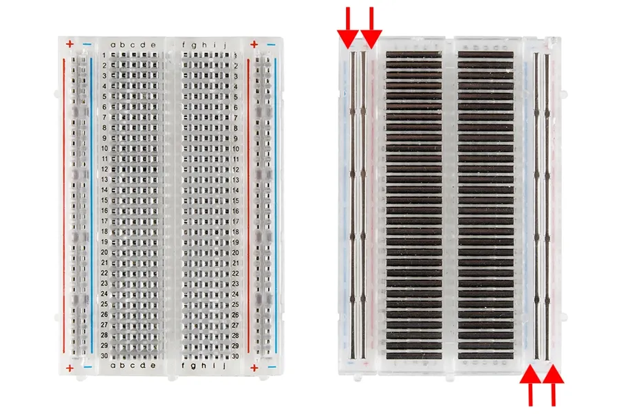
Solderless breadboards are fundamental tools for electronics prototyping, enabling the construction of circuits without soldering. Their internal structure, consisting of interconnected terminal and bus strips, facilitates efficient circuit assembly and modification. Understanding this structure is crucial for effective breadboard usage.
The typical solderless breadboard is composed of two primary types of connection points: terminal strips and bus strips. Terminal strips are the areas where most components are inserted, they consist of rows and columns of electrically connected contacts. Bus strips, usually located along the sides, provide continuous power and ground connections across the length of the board.
| Feature | Terminal Strips | Bus Strips |
|---|---|---|
| Location | Central part of the board | Sides of the board |
| Connectivity | Internally connected in rows (typically 5 connected points per row) | Internally connected in columns along the entire length |
| Purpose | Connect components for circuit elements | Provide power and ground distribution |
Key to understanding the structure is knowing that each row of 5 connected holes in the terminal strip are electrically common, but each row is isolated from the rows above and below. Similarly the bus strips are usually split in the middle on large breadboards, allowing for more than one supply voltage to be distributed. Often they are marked with red and blue to indicated positive and negative (or ground). Understanding the electrical connectivity within the solderless breadboard ensures accurate circuit construction and prevents short circuits, promoting efficient electronic prototyping.
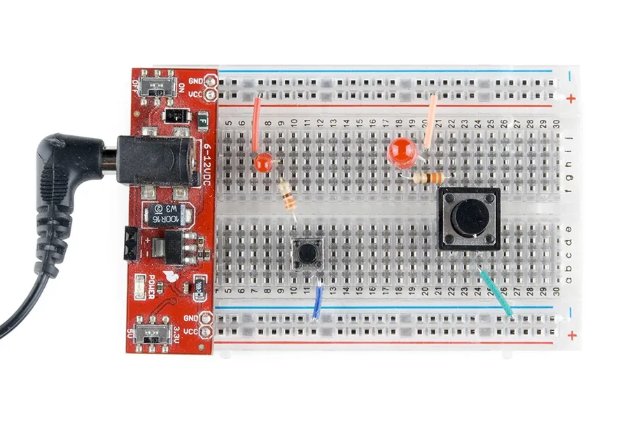
Successfully prototyping circuits on a solderless breadboard requires a solid understanding of how to securely place and connect basic electronic components. These components, such as resistors, capacitors, LEDs, and integrated circuits (ICs), are designed to fit snugly into the breadboard’s connection points, facilitating easy circuit construction and modification without soldering.
| Component | Description | Placement Guidelines |
|---|---|---|
| Resistors | Limit current flow in a circuit. They have color codes to indicate their resistance value. | Insert resistor leads into separate rows, spanning a gap in the center of the breadboard to connect different points in the circuit. |
| Capacitors | Store electrical energy. Come in various types like ceramic, electrolytic, and tantalum. | Place capacitor leads in separate rows similar to resistors, paying attention to polarity for electrolytic capacitors; longer lead typically denotes the positive terminal. |
| LEDs (Light Emitting Diodes) | Emit light when current flows through them. They have a specific polarity (+ and -). | Insert the longer (positive) lead (anode) and the shorter (negative) lead (cathode) into separate rows. Usually connected with a resistor in series to limit the current. |
| Integrated Circuits (ICs) | Contain complex circuits within them. They have multiple pins. | Align the IC over the center gap of the breadboard, straddling the gap with its pins on either side so each pin is in a unique row. It’s important to check IC pinouts in its datasheet. |
| Transistors | Used to amplify or switch electronic signals and power. | Each lead of a transistor (base, collector, emitter) must be inserted in separate rows, check its data sheet for pin layout |
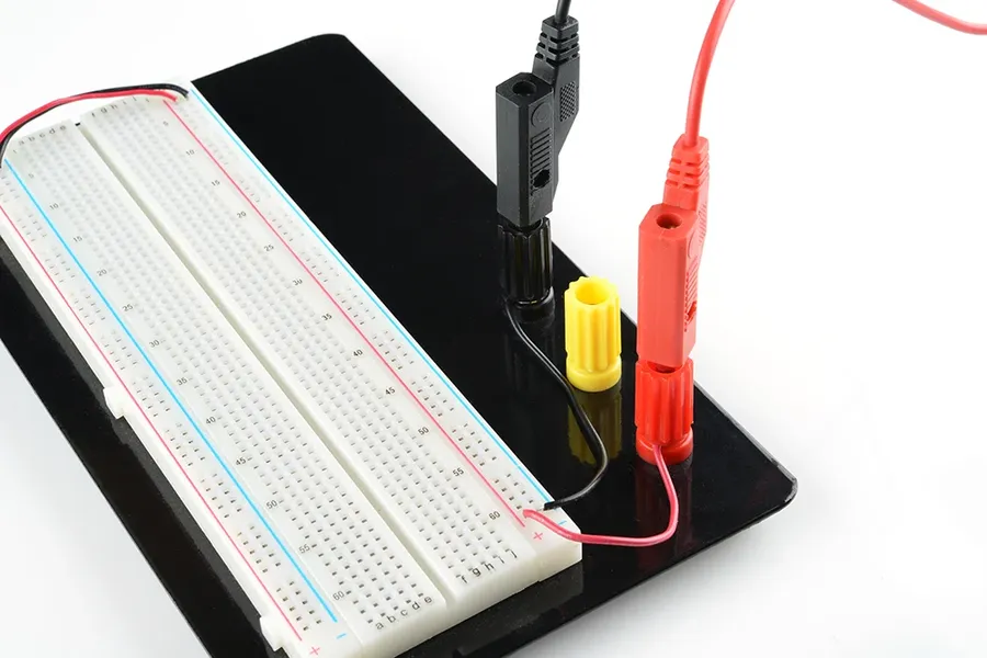
Effectively powering circuits on a solderless breadboard is crucial for reliable prototyping. This involves utilizing the breadboard's power rails (bus strips) to distribute consistent voltage and current throughout the circuit, ensuring all components receive the necessary power.
| Power Supply Option | Pros | Cons |
|---|---|---|
| DC Power Supply | Precise voltage and current control; stable output. | Less portable; Requires a dedicated power supply unit. |
| Battery | Portable; convenient for testing in various locations. | Limited lifespan; requires periodic replacement or recharging; voltage can drop as the battery discharges. |
| USB Power Adapter | Widely available; Convenient for low-voltage circuits. | May have limited current output compared to DC power supply; suitable for simpler circuits. |
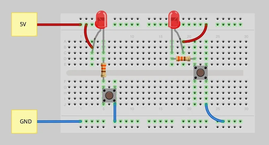
Constructing basic circuits on a solderless breadboard is a fundamental skill for electronics prototyping. This section details a step-by-step approach to building a simple LED circuit, focusing on proper component placement and connections. This practical example will clarify the breadboard's structure and how it facilitates circuit design without soldering.
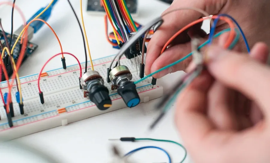
Solderless breadboards are the cornerstone of rapid electronic prototyping, offering distinct advantages over traditional soldering methods. Their flexibility, speed, reusability, and ease of use make them indispensable tools for beginners and experienced engineers alike. They facilitate the quick assembly and testing of electronic circuits without the permanence of soldering, allowing for dynamic modifications and experimentation.
Solderless breadboards and traditional soldering represent two distinct approaches to circuit construction, each with unique advantages and suitable applications. Solderless breadboards provide a flexible, reusable, and rapid prototyping environment, whereas soldering offers a more permanent, robust, and electrically reliable connection.
| Feature | Solderless Breadboard | Traditional Soldering |
|---|---|---|
| Connection Type | Temporary, pressure-fit | Permanent, fused metal |
| Reusability | Highly reusable, components easily relocated | Not reusable, requires desoldering for changes |
| Assembly Speed | Fast, no heating or melting required | Slower, requires heating and cooling time |
| Skill Level | Beginner-friendly, no prior experience needed | Requires skill and practice for proper technique |
| Electrical Reliability | Moderate, connections can be affected by movement | High, provides strong and stable connections |
| Suitability | Prototyping, testing, educational purposes | Permanent circuits, final product assembly |
| Cost | Relatively low, reusable | Low material cost, but tools might be expensive |
| Portability | Highly portable due to quick setup and teardown. | Less portable, especially when complex soldered connections are in place. |
| Durability | Components can be easily moved or accidentally dislodged. | More robust once completed, providing a more durable, permanent connection. |
In summary, solderless breadboards are indispensable for initial circuit design and experimentation due to their convenience and flexibility, while soldering is preferable when creating a final, long lasting and dependable circuit.
Effectively managing complex circuits on a solderless breadboard requires careful planning and execution. These advanced tips can help you build reliable and organized prototypes, improving both the efficiency of the build process and the ease of troubleshooting.
This section addresses common questions and concerns regarding solderless breadboards, providing practical insights into their usage, limitations, and suitability for various electronic projects. Understanding these frequently asked questions can enhance your experience and prevent common pitfalls when prototyping with solderless breadboards.
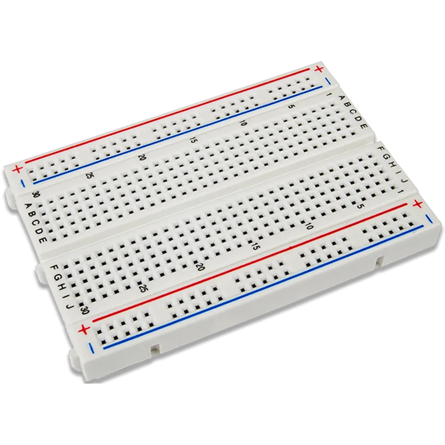
Selecting the appropriate solderless breadboard is crucial for efficient and effective prototyping. The ideal choice depends heavily on the project's scale and the complexity of the circuits involved. Breadboards are available in various sizes and configurations, each designed to accommodate different project requirements.
| Feature | Full-Size Breadboard | Half-Size Breadboard | Mini Breadboard |
|---|---|---|---|
| Tie Points | ~830 | ~400 | ~170 |
| Suitable Project Size | Large, complex | Medium | Small, simple |
| Power Rails | Typically included on both sides | Often included on both sides | Often omitted |
| Portability | Less Portable | Moderately portable | Highly portable |
Beyond size, consider the quality and construction. High-quality breadboards feature robust internal metal clips, ensuring reliable connections and longevity. Also, some breadboards are designed to be modular, allowing you to combine multiple units to form larger work surfaces. For beginners, a half-size breadboard is often a good starting point, providing ample space for basic projects. As projects become more ambitious, consider a full-size breadboard or a collection of smaller, modular boards.
The solderless breadboard is an indispensable tool for anyone venturing into the world of electronics. Its ease of use and reusability make it a perfect platform for beginners to experiment and for experienced engineers to quickly test ideas. By mastering the basic functions and best practices of a solderless breadboard, you can accelerate your learning, streamline your projects, and bring your electronic concepts to life with efficiency and precision. The future of electronics is bright and more accessible than ever, thanks to tools like the solderless breadboard.

