In the vast world of electronics, the 1N4007 diode stands as a fundamental component, much like the humble brick in construction. This seemingly simple semiconductor plays a crucial role in converting AC power to DC, a process vital to countless electronic devices we use daily. From your smartphone charger to larger industrial equipment, understanding the 1N4007 diode's function and capabilities is essential for anyone involved in electronics, whether as a hobbyist or a seasoned engineer. This article will explore the depths of the 1N4007, delving into its specifications, practical applications, and the science behind its operation, offering a clear and authoritative guide to this ubiquitous device.
Understanding the 1N4007 Diode Basics
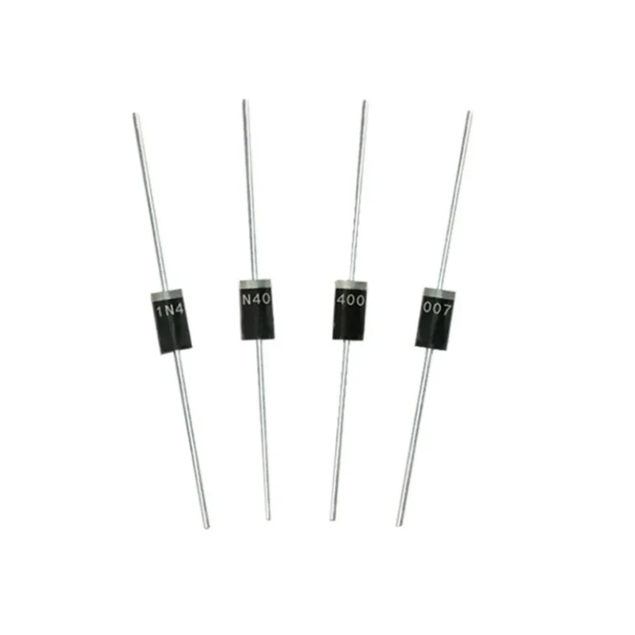
1N4007 Diode
The 1N4007 diode is a ubiquitous component in electronics, primarily employed as a silicon rectifier. Its fundamental function is to allow current to flow predominantly in one direction, a behavior crucial for converting alternating current (AC) to direct current (DC). This essential characteristic is achieved through its semiconductor construction and PN junction, forming a one-way valve for electrical current.
The 1N4007 is a silicon-based PN junction diode. It comprises a P-type semiconductor material (doped with impurities that create 'holes' or electron vacancies) and an N-type semiconductor material (doped with impurities that create excess free electrons). The junction where these two materials meet forms the heart of the diode, controlling its ability to conduct electricity. When a voltage is applied in the forward direction (positive to the P-side and negative to the N-side), electrons and holes move toward the junction, enabling current flow. In the reverse direction, the junction becomes a barrier, greatly limiting current flow.
Key Specifications and Parameters of the 1N4007
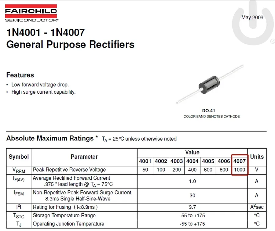
1N4007 Datasheet
The 1N4007 diode, a ubiquitous component in electronics, is defined by several key specifications and parameters that dictate its performance and suitability for various applications. Understanding these parameters is crucial for effective circuit design and reliable operation. This section provides a detailed breakdown of these essential characteristics.
Parameter
Symbol
Value
Unit
Description
Maximum Repetitive Reverse Voltage
VRRM
1000
V
The maximum reverse voltage that can be repeatedly applied across the diode without causing breakdown.
Maximum RMS Reverse Voltage
VR(RMS)
700
V
The maximum root mean square value of the reverse voltage.
Maximum DC Blocking Voltage
VR
1000
V
The maximum direct current voltage that can be applied in reverse bias.
Average Rectified Forward Current
IF(AV)
1
A
The average forward current that the diode can safely handle when conducting in the forward direction.
Peak Surge Current
IFSM
30
A
The maximum forward current the diode can withstand for a short duration (typically one half-cycle of a 60Hz sine wave) without damage.
Forward Voltage Drop
VF
1.1
V
The voltage drop across the diode when it is conducting in the forward direction (typically measured at 1A).
Reverse Leakage Current
IR
5
µA
The small current that flows through the diode when it is reverse-biased (typically measured at the maximum reverse voltage). This is also temperature dependent.
Operating Junction Temperature
Tj
-65 to +175
°C
The allowable range of temperature for the diode's internal junction.
Storage Temperature
TSTG
-65 to +175
°C
The allowable range of temperature for storing the diode.
These parameters are essential for engineers to correctly apply the 1N4007 in circuits. For example, exceeding the maximum repetitive reverse voltage can lead to diode breakdown, while exceeding the average rectified forward current will result in overheating and potential failure of the component. Furthermore, the forward voltage drop is an important parameter when calculating power losses in circuits. These specifications are typically tested and rated at 25°C, so designers should also consider the temperature dependence of these parameters in different operating environments.
Detailed Look at the 1N4007's Electrical Characteristics
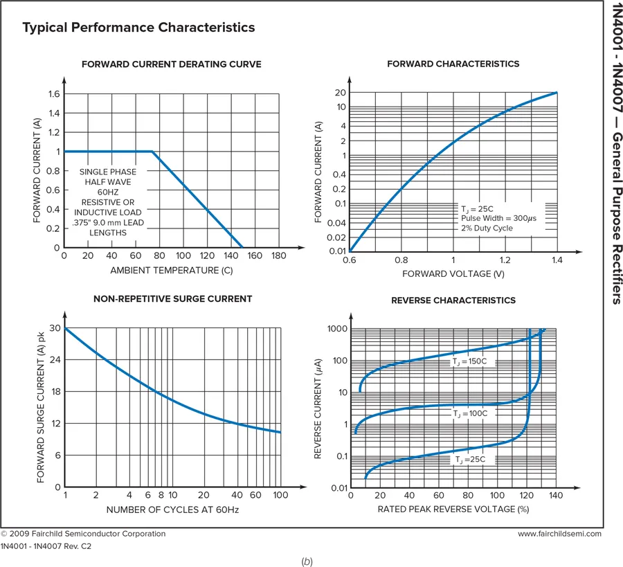
1N4007 Characteristics Graph
The 1N4007 diode's electrical behavior is fundamental to its application in various circuits. Its performance is characterized by distinct responses to both forward and reverse bias conditions, along with sensitivities to temperature changes and specific switching characteristics. Understanding these parameters is critical for reliable circuit design and operation.
This section will explore how the 1N4007's electrical characteristics change with varying voltage levels, temperature, and switching speeds.
Characteristic
Description
Typical Value
Unit
Forward Voltage (Vf)
Voltage drop across the diode when conducting in forward bias.
0.7 - 1.1
V
Reverse Leakage Current (Ir)
Small current flowing through the diode when in reverse bias.
5
μA
Maximum Forward Current (If)
The maximum continuous current the diode can handle without damage.
1.0
A
Maximum Peak Surge Current (Ifsm)
The maximum non-repetitive current the diode can handle for a short duration.
30
A
Maximum Repetitive Reverse Voltage (Vrm)
The peak reverse voltage the diode can withstand without breakdown.
1000
V
Operating Junction Temperature (Tj)
The allowable temperature range for the diode's semiconductor junction.
-65 to +150
°C
The forward voltage (Vf) across a 1N4007 diode increases with forward current and temperature, while the reverse leakage current (Ir) is greatly influenced by temperature, generally increasing with a higher temperature. Switching speed is limited by the diode's construction, causing a delay when transitioning from forward conduction to reverse blocking. These characteristics impact the diode's performance in circuits and need careful consideration in design.
Practical Applications of the 1N4007 Diode
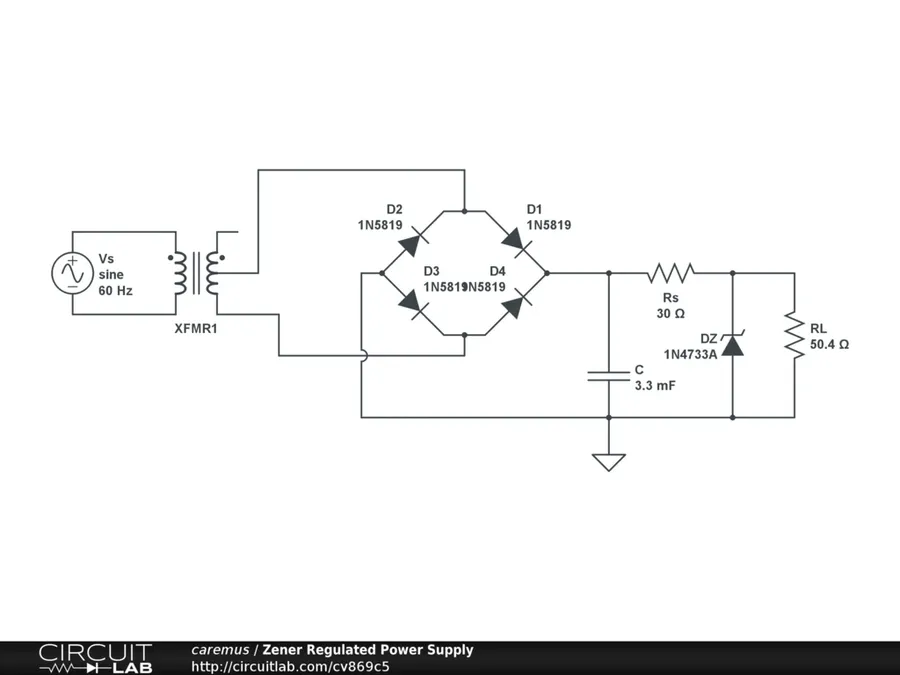
Power Supply Circuit
The 1N4007 diode, a ubiquitous component in electronics, finds its utility across numerous applications due to its robust performance as a general-purpose silicon rectifier. Its ability to efficiently convert AC to DC power, coupled with its high reverse voltage capability, makes it suitable for diverse circuit designs.
Power Supplies In power supplies, the 1N4007 is a crucial component in rectifier circuits. It converts the incoming AC voltage from the mains into a pulsating DC voltage, which is then smoothed by capacitors and regulated to provide a stable DC output for electronic devices. For example, it's used in the bridge rectifier stage to convert AC from a wall outlet to DC for charging cell phones and powering laptops.
AC-DC Converters The 1N4007 diode is fundamental in AC-DC converters, which are essential in various electronic devices for converting the alternating current from the power grid to the direct current required by the device's internal circuitry. These converters utilize the diode’s ability to allow current to flow in only one direction, effectively turning the AC waveform into a DC waveform.
Freewheeling Diodes In inductive circuits, such as those containing relays or motors, the 1N4007 serves as a freewheeling or flyback diode. When the current flowing through an inductor is interrupted, the magnetic field collapses, inducing a high-voltage spike. The 1N4007 diode provides a path for this current, preventing damage to other circuit components. Consider its use in a simple relay circuit where the 1N4007 prevents the relay coil's back EMF from damaging the transistor switch.
Protection Circuits The 1N4007 is used in protection circuits to safeguard sensitive electronic components from reverse voltage conditions. By placing it in series with a power supply, any accidental reverse voltage will be blocked, preventing damage to downstream components. For instance, in a power adapter with a polarized connector, it will stop the device from functioning in case the connection polarity is incorrectly reversed.
1N4007 Diode vs. Other Diodes: A Comparison
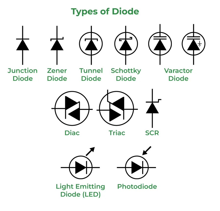
Various Types of Diodes
The 1N4007 is a widely used rectifier diode, but understanding how it compares to other common diodes is crucial for effective circuit design. This section provides a detailed comparison of the 1N4007 with other frequently used diodes, highlighting key differences in their specifications, applications, and overall advantages and disadvantages.
Characteristic
1N4007
1N4001
1N4148
1N5819
Maximum Repetitive Reverse Voltage
1000V
50V
100V
40V
Average Rectified Forward Current
1A
1A
0.2A
1A
Peak Surge Current
30A
30A
1A
30A
Forward Voltage Drop (typical)
1.1V
0.93V
0.715V
0.45V
Reverse Leakage Current (typical)
5uA
5uA
5uA
5uA
Primary Application
General purpose rectification
General purpose rectification
High-speed switching
Schottky diode, low voltage rectification
Advantages
High reverse voltage, robust
Lower cost, common
Fast switching speed, low capacitance
Very low forward voltage drop
Disadvantages
Higher forward voltage drop
Lower reverse voltage
Lower current capacity
Lower reverse voltage capability
Proper Handling and Installation of the 1N4007 Diode
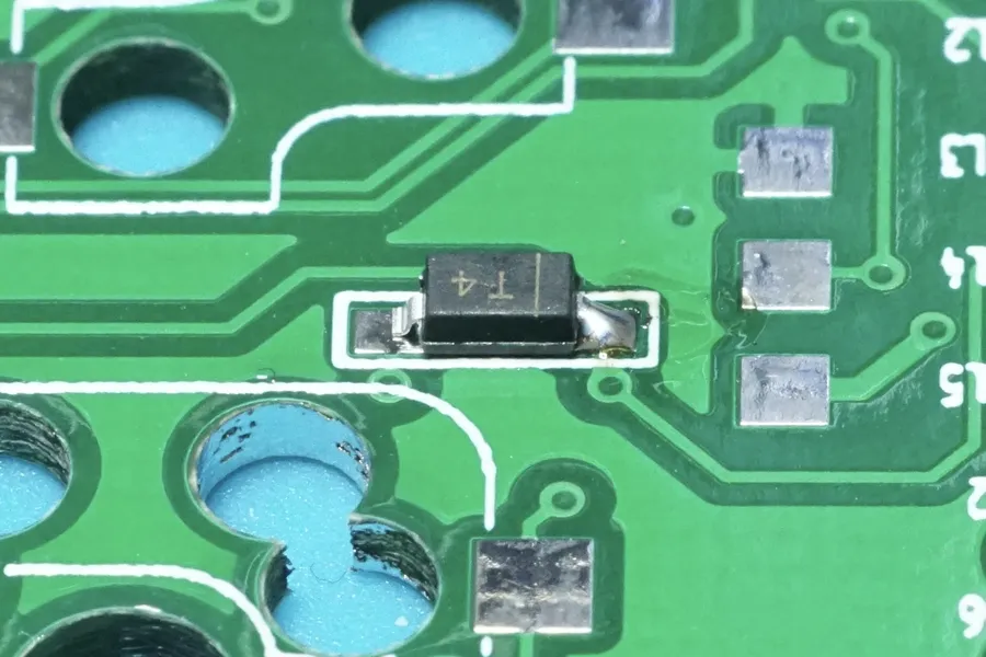
Soldering Diode
The 1N4007 diode, while robust in operation, requires careful handling and proper installation techniques to prevent damage and ensure reliable performance within electronic circuits. Attention to storage conditions, handling practices, and soldering procedures is critical for maintaining the integrity of the diode and the overall functionality of the circuit.
Storage Conditions Store 1N4007 diodes in a dry, temperature-controlled environment, away from direct sunlight and extreme temperatures, typically between -65°C to 175°C. Avoid excessive humidity to prevent corrosion of the leads. Proper storage ensures the electrical parameters remain stable.
Handling Precautions Avoid physically stressing the diode body or leads, as this can lead to internal damage or fracture of the semiconductor material. ESD (Electrostatic Discharge) protection, such as using antistatic wrist straps and mats, is highly recommended during handling. A static discharge can cause immediate and latent damage.
Lead Preparation When preparing the leads for soldering, use appropriate tools like lead bending tools or pliers to minimize stress on the diode body. Avoid bending leads too close to the diode body, as this can crack the diode and affect its internal structure.
Soldering Techniques Use a soldering iron with temperature control. A typical range of 300°C to 350°C is advisable to minimize the risk of overheating the diode. Solder quickly and efficiently, avoiding prolonged exposure of the diode to high temperatures. Applying a heat sink during soldering is a recommended practice to manage heat.
Orientation Ensure the 1N4007 is installed with the correct polarity within the circuit. The cathode end of the diode is typically marked with a band (usually white or silver). Incorrect polarity can result in the diode not performing its rectifying function and causing damage to other circuit components or even diode failure.
Post-Installation Inspection Visually inspect the soldered joints for any issues such as cold solder joints, solder bridges, or excessive solder. Use a multimeter to check the diode's forward voltage drop (typically 0.7V for silicon diodes), and to ensure it is not shorted or open circuit after installation. This ensures the diode is in the right direction and properly installed.
Troubleshooting Common Issues with the 1N4007 Diode
The 1N4007 diode, while robust, can exhibit issues in circuits, typically manifesting as overheating, reverse leakage, or outright failure. Proper diagnosis and understanding of these problems are crucial for maintaining circuit integrity and reliability. This section outlines common problems, their causes and effective diagnostic and resolution strategies.
Overheating Overheating in a 1N4007 is typically caused by excessive forward current, exceeding the diode's rated average rectified forward current of 1A, or inadequate heat dissipation. If the diode is not mounted correctly or the ambient temperature is too high, the diode's thermal resistance will lead to higher junction temperature. Diagnosing this involves checking the circuit current and ensuring that the diode is adequately heatsinked, also ensure the device is operating within the maximum temperature ratings. It is crucial to operate the 1N4007 within its specified operating temperature range, typically -65°C to +175°C, to prevent thermal damage.
Excessive Reverse Leakage Current While designed to block current in the reverse direction, a small leakage current is normal. However, if this reverse leakage current becomes excessive, it indicates a damaged or stressed diode. This issue can be identified by measuring the current in the reverse direction under a reverse voltage below the maximum repetitive reverse voltage and can be caused by excessive reverse voltage application. Leakage current increases significantly with temperature, so this should be tested at the operational temperature.
Diode Failure (Open or Short) Diode failure can manifest as either an open circuit (no conduction in either direction) or a short circuit (conduction in both directions). This often results from electrical overstress, excessive current or voltage, or thermal stress from the conditions as explained above. Diagnosis requires a multimeter to check for continuity in both forward and reverse directions. An ideal diode shows low resistance (near 0 ohms) when forward biased and extremely high resistance when reverse biased. A short circuit will show low resistance in both directions, whereas an open circuit shows no conductivity in either direction. In both of these cases, the diode will require replacement with a new 1N4007.
Transient Voltage Spikes Transient voltage spikes can cause immediate damage or gradual degradation of a diode's performance. These spikes are often caused by inductive loads and can exceed the diode's reverse voltage rating. Using a transient voltage suppressor or a snubber circuit may be necessary to protect the 1N4007. A thorough analysis of the circuit to determine the source of the transient overvoltage will aid in solving this problem.
Improper Soldering Incorrect soldering can cause damage to the diode. Prolonged exposure to high soldering temperatures or excessive physical pressure during soldering can cause mechanical or electrical damage, resulting in intermittent or total failure. Ensuring that the manufacturer's recommendations for soldering are adhered to will help prevent this. Employing proper technique with the correct soldering temperature and time will keep the device from overheating during the soldering process.
Frequently Asked Questions about 1N4007 Diodes
This section addresses common inquiries regarding the 1N4007 diode, providing clear and concise answers to frequently asked questions by engineers and hobbyists alike.
What is the primary function of a 1N4007 diode? The 1N4007 is primarily used as a general-purpose rectifier diode. Its main function is to allow current to flow in one direction while blocking it in the opposite direction. This makes it crucial in converting AC to DC power and in various signal processing applications.
What is the maximum current a 1N4007 diode can handle? The 1N4007 diode has a maximum average rectified forward current rating of 1 Ampere (1A). It also has a peak surge current rating of 30 Amperes (30A), but this is a non-repetitive surge rating and cannot be sustained continuously.
What is the typical forward voltage drop across a 1N4007 diode? The forward voltage drop across a 1N4007 diode is typically around 0.7 to 1.1 volts when it's conducting. This voltage drop is temperature dependent, decreasing slightly with increased temperature.
How does the 1N4007 differ from the 1N4001 diode? The primary difference between the 1N4007 and the 1N4001 is their maximum repetitive reverse voltage ratings. The 1N4007 has a rating of 1000V, whereas the 1N4001 has a rating of 50V. Both have similar current handling capacities but their use cases are determined by the voltage requirements of the application.
What is the reverse leakage current of a 1N4007 diode? The reverse leakage current for a 1N4007 diode is typically very low, measured in microamperes (µA). This leakage current increases with temperature, but it should remain minimal under normal operating conditions.
Can a 1N4007 diode be used as a Zener diode? No, a 1N4007 diode should not be used as a Zener diode. Zener diodes are specifically designed to operate in reverse breakdown, with a controlled breakdown voltage. The 1N4007 is a rectifier diode and its reverse characteristics are not intended for controlled breakdown behavior.
What are some common applications for the 1N4007 diode? The 1N4007 diode finds extensive use in AC to DC power supplies, acting as a rectifier to convert AC power to DC. It's also used in freewheeling diode applications where it protects sensitive circuits from inductive kickback. Additionally, it is utilized in basic signal rectification and general circuit protection.
The 1N4007 diode, though small, is a workhorse in the electronics world. From rectifying power in simple adapters to serving as a crucial component in complex systems, its versatility and reliability are undeniable. By understanding the principles of its operation, specifications, and best practices for usage, one can effectively leverage this component in a wide array of applications. Whether you are a seasoned electronics enthusiast or a student, the 1N4007 remains an essential component to understand, showcasing the simple yet elegant design of the semiconductor devices that power our modern world. The 1N4007 diode is more than just a component; it's a gateway to understanding the magic of electronics.