In the fascinating universe of electronics, the 47uF capacitor is a seemingly humble component that plays a pivotal role in countless circuits. Just as a heart regulates blood flow in our bodies, the 47uF capacitor smooths electrical currents, filters noise, and stores energy, impacting everything from smartphones to power supplies. This article will guide you through the crucial aspects of 47uF capacitors, enabling you to understand their characteristics, selection criteria and practical applications.
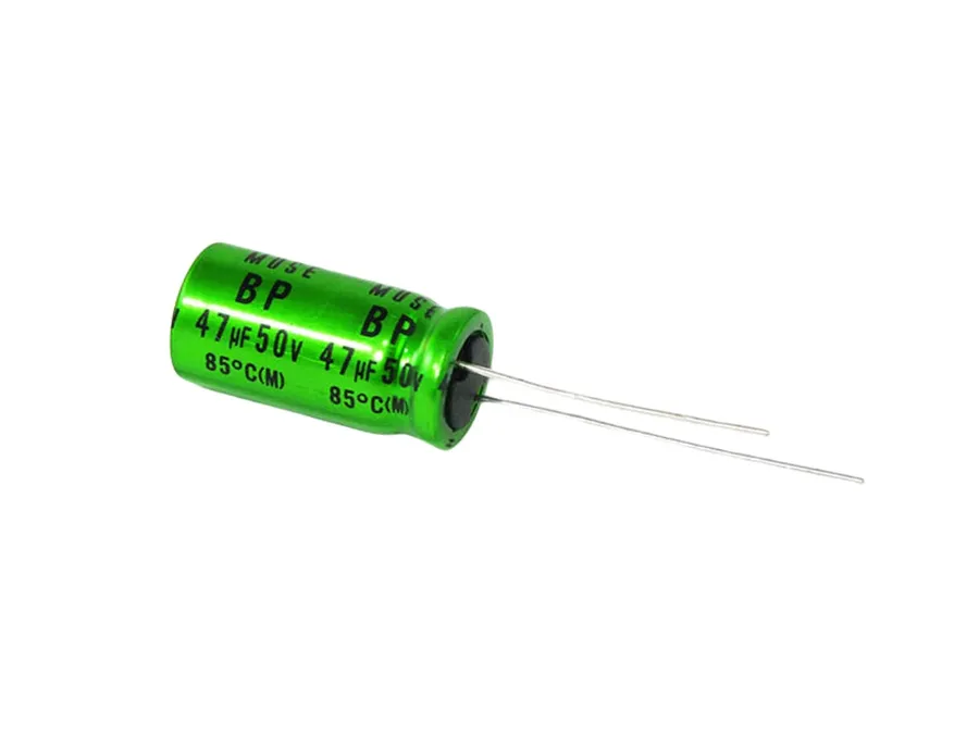
At its core, a 47uF capacitor is an electronic component designed to store electrical energy within an electric field. The '47uF' designation specifies its capacitance value, indicating a storage capacity of 47 microfarads. Capacitance, measured in farads (F), quantifies the amount of electric charge a capacitor can store per unit voltage. A microfarad (uF) is one millionth of a farad (10^-6 F), signifying that a 47uF capacitor stores a relatively small but significant amount of charge, making it a key component in many electronic circuits for filtering, smoothing, and timing purposes.
| Term | Description |
|---|---|
| Capacitance | The ability of a component to store an electrical charge. |
| Farad (F) | The base unit of capacitance, representing a large amount of storage. |
| Microfarad (uF) | A subunit of capacitance, one millionth of a farad (10^-6 F). |
| 47uF | Denotes a capacitor with a capacitance value of 47 microfarads. |
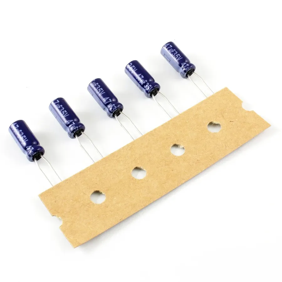
The 47uF capacitor, a cornerstone of many electronic circuits, is not a monolithic entity. It comes in several varieties, each with unique characteristics that make it suitable for specific applications. Understanding these differences is crucial for effective circuit design and troubleshooting. The primary types include electrolytic, ceramic, tantalum, and film capacitors, each distinguished by their construction, material properties, and performance.
| Capacitor Type | Construction | Pros | Cons | Typical Applications |
|---|---|---|---|---|
| Electrolytic | Uses an electrolyte (liquid or solid) as one of its electrodes. | High capacitance per volume, relatively low cost. | Polarized, limited lifespan, higher ESR (Equivalent Series Resistance) and ESL (Equivalent Series Inductance). | Power supply filtering, decoupling, audio circuits. |
| Ceramic | Uses a ceramic dielectric material. | Non-polarized, low cost, low ESR and ESL, wide temperature range. | Lower capacitance values compared to electrolytics, capacitance can change with temperature and voltage. | High frequency filtering, decoupling, bypass applications. |
| Tantalum | Uses tantalum pentoxide as the dielectric. | High capacitance in small size, good stability, low ESR. | Polarized, more expensive than electrolytics, susceptible to damage from voltage spikes, can fail catastrophically. | Critical applications where stability and small size is important, portable electronics. |
| Film | Uses a thin plastic film as the dielectric. | High precision, stable, low ESR and ESL, good for high voltage applications. | Larger size compared to other types, higher cost. | Audio applications, high precision filtering, power applications. |
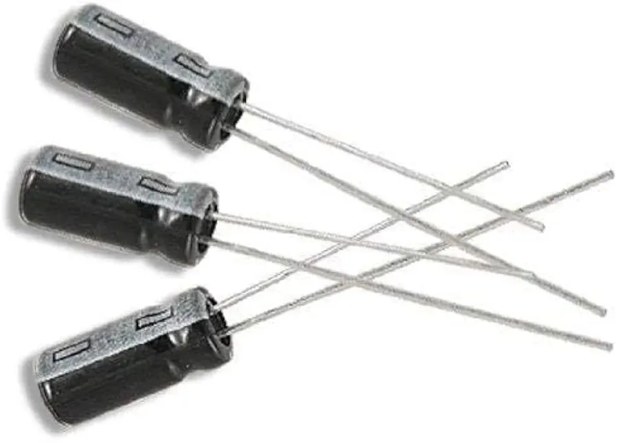
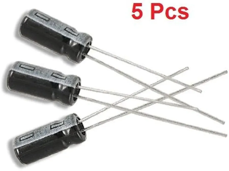
47uF electrolytic capacitors are commonly found in two lead configurations: axial and radial. These configurations dictate how the capacitor is mounted onto a circuit board and each design offers distinct advantages and disadvantages for specific applications.
| Feature | Axial Lead 47uF Electrolytic Capacitor | Radial Lead 47uF Electrolytic Capacitor |
|---|---|---|
| Lead Orientation | Leads extend from opposite ends of the capacitor body. | Leads extend from the same end of the capacitor body. |
| Mounting Style | Typically mounted horizontally on the circuit board. | Typically mounted vertically on the circuit board. |
| Space Efficiency | May occupy more linear space on the board. | Generally more space-efficient for dense boards. |
| Mechanical Stability | Can be more robust against physical stress if supported properly. | May be more vulnerable to stress, especially with larger capacitor bodies. |
| Typical Applications | Older equipment, through-hole PCB designs where horizontal mounting is feasible. | Modern, densely populated PCBs; often used for bulk capacitance in power supplies and signal processing circuits. |
| Cost | Slightly less common, may sometimes be slightly more expensive due to reduced demand. | More common, generally lower cost due to higher demand and ease of manufacturing. |
The choice between axial and radial 47uF electrolytic capacitors often depends on the specific design requirements of the circuit board. Radial capacitors are preferred in modern designs due to their compact nature, while axial capacitors are more suited to older designs and applications with horizontal space constraints.
Understanding the critical specifications of a 47uF capacitor is paramount for ensuring proper circuit functionality and longevity. These specifications, primarily voltage rating, tolerance, and operating temperature range, dictate the capacitor's performance limits and suitability for different applications. Selecting a capacitor that doesn't meet these requirements can lead to component failure and circuit malfunctions.
| Specification | Description | Impact on Functionality | Example |
|---|---|---|---|
| Voltage Rating | The maximum voltage that the capacitor can safely withstand without dielectric breakdown. | Exceeding the voltage rating can cause irreversible damage, leading to short circuits, component failure and potential fire hazard. Operating below the voltage rating ensures reliable operation. | A 50V capacitor should not be used in a 100V circuit. |
| Tolerance | The permissible deviation from the nominal capacitance value (47uF in this case), typically expressed as a percentage. | High tolerance can lead to variations in circuit behavior, causing inaccurate timing and incorrect signal filtering. Tighter tolerances result in more predictable circuit behavior, but typically come at a higher cost. | A ±20% tolerance means a 47uF capacitor can have a capacitance value between 37.6uF and 56.4uF. |
| Temperature Range | The range of temperatures over which the capacitor is designed to operate reliably without significant degradation. | Operating beyond the specified temperature limits can cause the capacitance value to shift, accelerate aging, cause electrolyte to dry out, and lead to premature failure. Operating within the temperature range ensures stable performance and long operational life. | A capacitor rated for 105°C should be used in high-temperature applications, while an 85°C rated capacitor would be suitable in less demanding environment. |
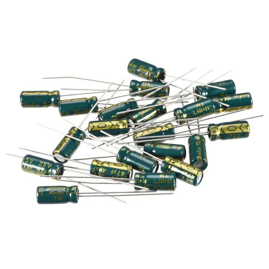
The 47uF capacitor is a versatile component found in a wide array of electronic circuits, primarily due to its ability to store a moderate amount of charge and its relatively compact size. Its applications span from power conditioning to signal processing, making it a staple in both simple and complex electronic designs. The capacitance value of 47uF is particularly suitable for applications where moderate energy storage or filtering is required, striking a balance between energy capacity and response speed. This makes it useful in a broad range of scenarios in power electronics and signal processing.
Selecting the correct 47uF capacitor is crucial for optimal circuit performance and reliability. This guide provides a structured approach to ensure you choose the most appropriate capacitor for your specific application, considering various factors like operating voltage, temperature, and physical dimensions.
Replacing a 47uF capacitor requires careful consideration of several factors to ensure the proper functionality and longevity of the electronic circuit. It is not always a simple swap; understanding the nuances of capacitor characteristics is critical for a successful replacement.
When replacing a 47uF capacitor, it is imperative to match or exceed the original specifications to avoid potential issues. These specifications primarily include the capacitance value (47uF), voltage rating, tolerance, and temperature range. Using a capacitor with lower voltage or temperature ratings can lead to premature failure, while significantly exceeding the capacitance value might negatively affect circuit behavior.
When selecting a compatible replacement, carefully consider the capacitor's type (e.g., electrolytic, ceramic, tantalum). Each type possesses distinct properties. For example, electrolytic capacitors have high capacitance values in small sizes, while ceramic capacitors offer greater stability at higher frequencies. Therefore, swapping between types could have implications. Similarly, physical dimensions are important as a large capacitor may not fit in the space intended for a smaller one.
While some variance is tolerable, significant deviations from the original capacitance value are typically not recommended. A higher capacitance can lead to slower charging/discharging times, possibly impacting timing circuits or causing unexpected behavior with filtering. Conversely, a lower capacitance might be insufficient for its intended function, such as in power supply smoothing applications, resulting in increased noise and ripple.
When sourcing a replacement, ensure the new capacitor matches or exceeds the original specifications. Using a capacitor with a higher voltage rating than the original is generally acceptable and can enhance reliability by providing a greater safety margin. Always check the datasheet for details on ESR(Equivalent Series Resistance), and operating temperature of the substitute component to ensure it is within operating parameters of the original capacitor.
This section addresses common questions regarding 47uF capacitors, providing clear and concise answers to help users understand their usage, characteristics, and proper application.
A comparative analysis of various 47uF capacitor types provides critical insights for engineers and designers. The selection of a 47uF capacitor hinges on the application's demands, encompassing factors such as cost, operating conditions, and performance metrics.
| Capacitor Type | Pros | Cons | Typical Applications | Average Cost Range (USD) |
|---|---|---|---|---|
| Electrolytic (Aluminum) | High capacitance per volume, relatively inexpensive | Polarized (requires correct orientation), limited lifespan, higher ESR (Equivalent Series Resistance), sensitive to temperature | Power supply filtering, decoupling, audio coupling | 0.05 - 0.50 |
| Ceramic (Multilayer) | Low ESR, non-polarized, small size, high-frequency performance | Capacitance changes with voltage and temperature, lower capacitance values compared to electrolytic, may have piezo-electric effects | Bypassing, filtering, signal coupling | 0.02 - 0.20 |
| Tantalum | High capacitance per volume, more stable than aluminum electrolytic, good temperature stability | Polarized, more expensive than electrolytic and ceramic, can fail catastrophically if overstressed, sensitive to reverse voltage | High reliability applications, filtering in low voltage circuits, data storage systems | 0.10 - 1.00 |
| Film (Polyester, Polypropylene) | Non-polarized, low ESR, high voltage rating, good stability | Larger physical size than ceramic, higher cost | Audio applications, high frequency filtering, precision timing circuits | 0.20 - 2.00 |
The 47uF capacitor is a versatile electronic component crucial for many applications, from simple circuits to complex systems. Its role in filtering, smoothing, and energy storage makes it indispensable. With a clear understanding of its different types, specifications, and selection criteria, choosing the right 47uF capacitor for your specific needs becomes a much simpler task, ensuring the reliability and performance of your electronics. Keep exploring and learning about electronic components, just as there is always a new connection to be discovered in our world of interconnectedness, the role of the 47uF capacitor is that of a connecting point in the circuit.

