10nF to uF: A Comprehensive Guide to Capacitor Conversion
2025.02.06
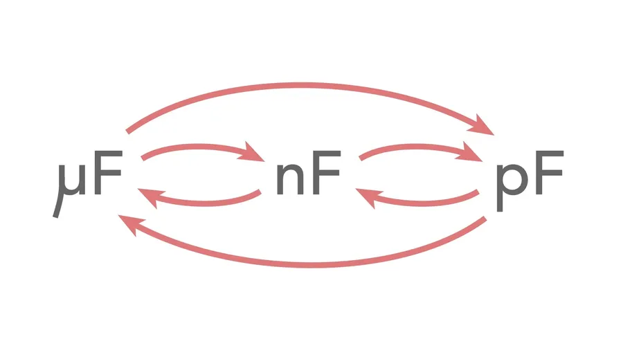
In the realm of electronics, understanding capacitance and its units is crucial for both hobbyists and professionals. Capacitors, measured in farads (F), often use prefixes like micro (µF), nano (nF), and pico (pF) to represent their values. Knowing how to seamlessly convert between these units is essential for reading schematics, repairing circuits, and selecting the right components. This guide will specifically focus on the conversion between 10 nanofarads (10nF) to microfarads (µF), providing you with practical knowledge and tools.
Understanding Capacitance Units: Farads, Microfarads, and Nanofarads
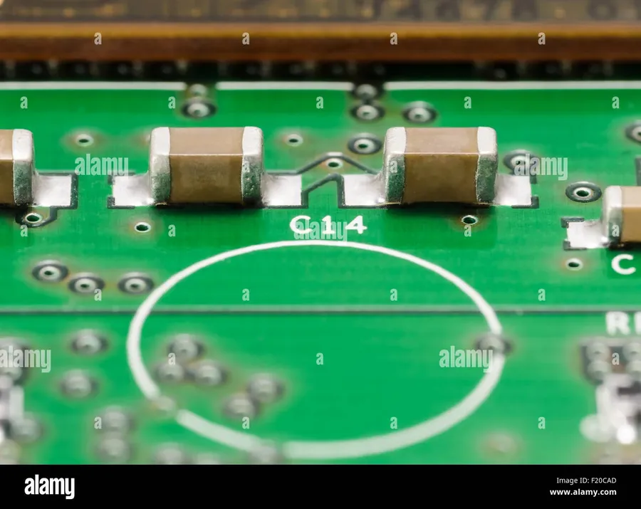
SMD Capacitor on PCB
Capacitance, measured in farads (F), quantifies a component's ability to store an electrical charge. The farad, however, is a large unit, hence, microfarads (µF) and nanofarads (nF) are commonly employed for practical applications in electronics. These sub-units are critical in understanding and working with capacitors in circuit design and analysis.
Farad (F) The base unit of capacitance. A capacitor with a capacitance of 1 farad stores 1 coulomb of charge when a voltage of 1 volt is applied. Due to its large scale, the farad is rarely used in practical electronic applications.
Microfarad (µF) A microfarad is one millionth (10⁻⁶) of a farad. This unit is widely used for capacitors in various applications. The conversion factor to farads is 1 µF = 1 x 10⁻⁶ F.
Nanofarad (nF) A nanofarad is one billionth (10⁻⁹) of a farad. Nanofarads are also commonly encountered, particularly in high-frequency circuits and smaller value capacitors. The conversion factor to farads is 1 nF = 1 x 10⁻⁹ F.
Unit
Symbol
Conversion to Farads (F)
Farad
F
1 F
Microfarad
µF
10⁻⁶ F
Nanofarad
nF
10⁻⁹ F
The Conversion Formula: nF to uF
Converting capacitance values between nanofarads (nF) and microfarads (µF) is a common task in electronics. The relationship between these units is based on powers of ten. A microfarad (µF) is 1000 times larger than a nanofarad (nF), therefore the conversion involves dividing by 1000.
The formula for converting nanofarads (nF) to microfarads (µF) is expressed as:
µF = nF / 1000
This formula is derived from the metric prefixes: 'nano' represents 10⁻⁹ and 'micro' represents 10⁻⁶. Therefore, 1 µF = 10⁻⁶ F and 1 nF = 10⁻⁹ F. To convert from nF to µF, we divide by the ratio of these prefixes, which is 10⁻⁶ / 10⁻⁹ = 10³. Thus, dividing by 1000 effectively scales the nanofarad value up to its equivalent microfarad value.
For example, if you have 2000 nF, dividing by 1000 will give you 2 µF. This simple division allows for quick and accurate conversions between nanofarads and microfarads.
10nF to uF: The Specific Conversion
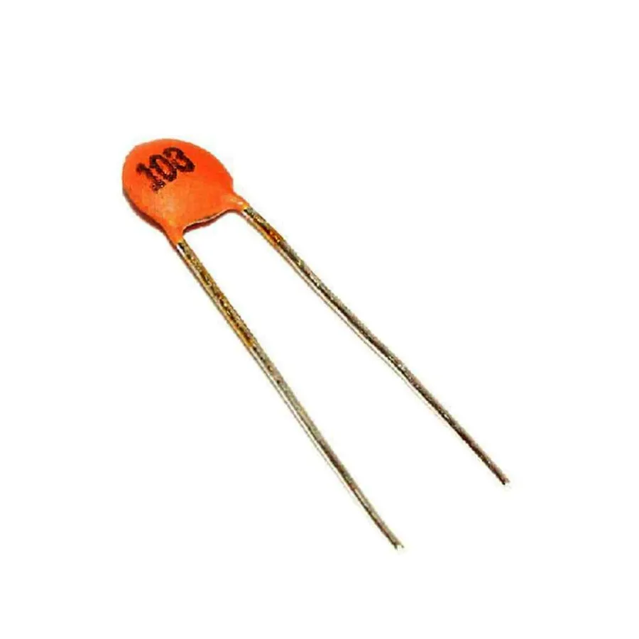
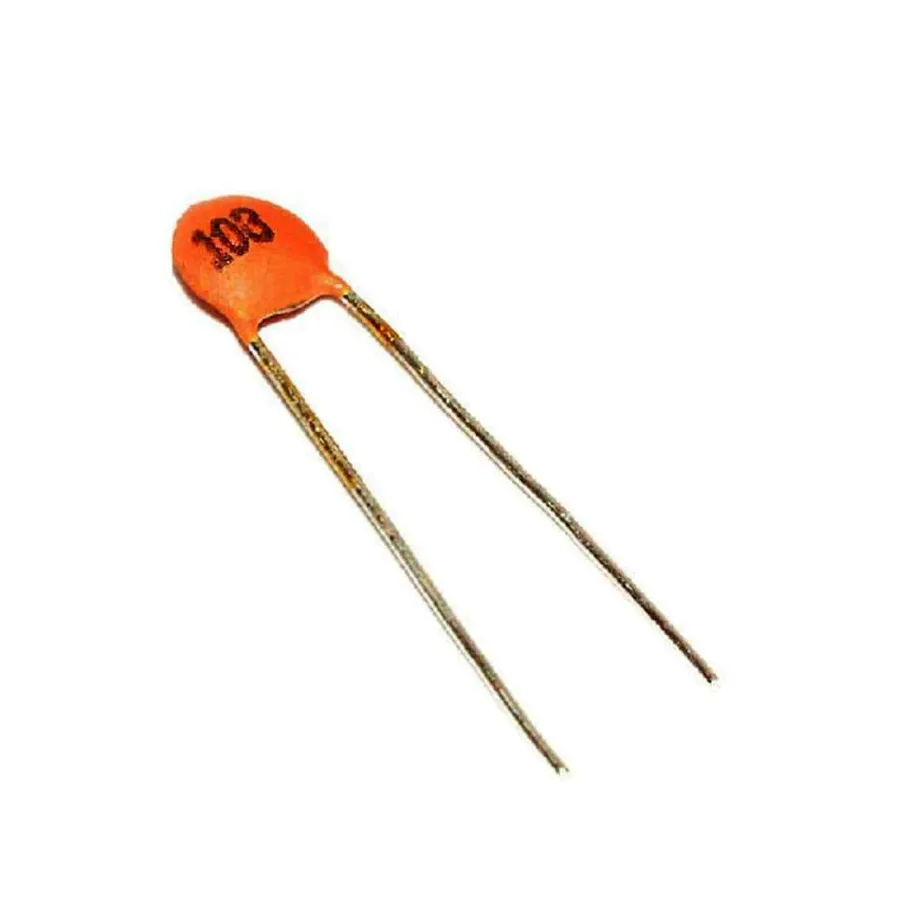
10nF Ceramic Capacitor
Converting 10 nanofarads (nF) to microfarads (µF) is a straightforward process using the fundamental relationship between these capacitance units. Since 1 microfarad is equal to 1000 nanofarads, the conversion involves dividing the value in nanofarads by 1000.
The formula for the conversion is:
µF = nF / 1000
Applying this to our specific case, we calculate:
µF = 10 nF / 1000
µF = 0.01 µF
Therefore, 10 nanofarads is equivalent to 0.01 microfarads. This result underscores the relative magnitude of nanofarads compared to microfarads, where a microfarad represents a significantly larger capacitance value.
Practical Examples of 10nF Capacitors
10nF Capacitor in Circuit
10nF capacitors, while seemingly small, play crucial roles in various electronic circuits. Their size makes them ideal for applications where space is a constraint, and their capacitance value is well-suited for tasks involving high-frequency signal processing and timing.
Here are some common applications where 10nF capacitors are frequently employed:
Bypassing Capacitors In digital circuits, 10nF capacitors are often used as bypass capacitors (also known as decoupling capacitors). Placed close to integrated circuits (ICs), they provide a local charge reservoir to suppress high-frequency noise on the power supply lines, ensuring stable operation of the ICs. This helps to prevent erratic behavior or signal corruption due to voltage fluctuations. This is a crucial element for the smooth operation of digital electronics, such as microcontrollers and digital logic gates.
Filtering Applications 10nF capacitors are utilized in filtering circuits, typically as part of low-pass or high-pass filters. In these applications, they help to pass or block specific frequency ranges within an electronic signal. They are frequently used in audio circuits to reduce noise and unwanted high frequencies in audio signals. The capacitor's interaction with resistors determines the cut-off frequency of these filters, making the precise value of 10nF important to achieve the desired filtering characteristics.
Timing Circuits 10nF capacitors are also used in timing circuits, such as RC (Resistor-Capacitor) oscillators and monostable multivibrators (also known as one-shots). The capacitor's charging and discharging behavior is used to create precise time delays. The 10nF value, along with a carefully chosen resistor value, enables time delays or pulse widths in the microsecond to millisecond range. These types of circuits are the heart of many applications, from producing clock signals to signal timing for digital devices and other applications where time intervals have to be controlled.
Sample and Hold Circuits In sample-and-hold circuits, 10nF capacitors are used to hold an analog voltage level for a short period. These circuits are used in data acquisition systems and analog-to-digital converters. The 10nF capacitor stores the analog signal until it can be converted into a digital value. The capacitor’s ability to hold the charge accurately is a critical characteristic in this application.
High Frequency coupling In high-frequency circuits, 10nF capacitors are often used for AC coupling. These types of capacitors allow alternating current (AC) signals to pass through while blocking any direct current (DC) component. This is particularly useful for isolating different parts of the circuit and in signal amplifier stages. This blocking of DC components can prevent saturation and improve the overall system performance.
The selection of a 10nF capacitor is not only determined by its capacitance but also by other factors, such as its voltage rating, temperature coefficient, and tolerance. The application context will dictate the precision and component characteristics required for the application
Capacitor Conversion Chart: uF, nF, and pF
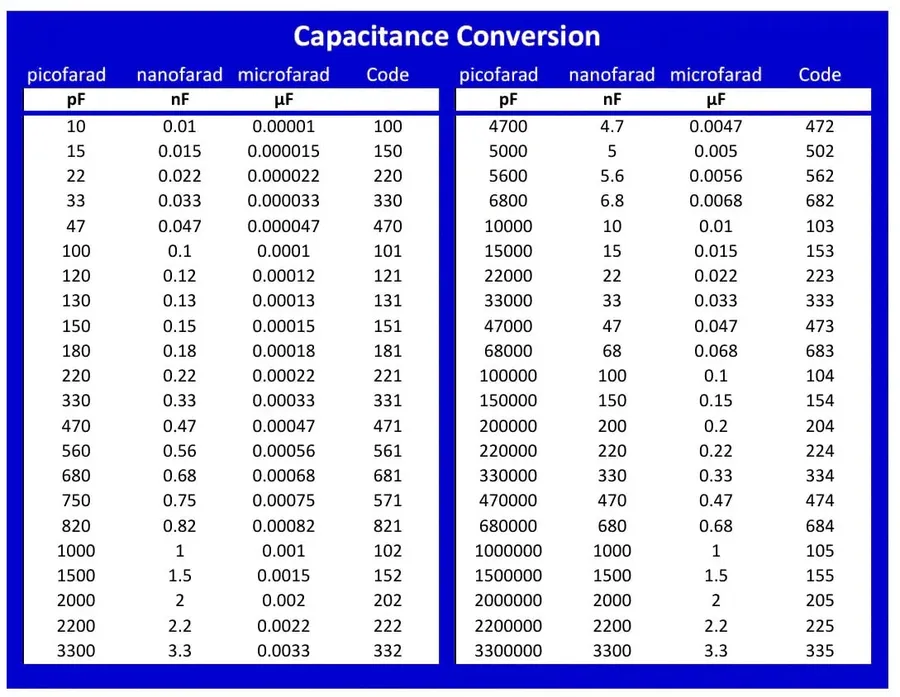
Capacitor Unit Conversion Chart
Navigating between different capacitance units—microfarads (uF), nanofarads (nF), and picofarads (pF)—can be streamlined using a conversion chart. This section provides a comprehensive table for quick reference, enabling easy transitions between these common units used in electronics. This chart will be particularly useful when working with various components where capacitance values are expressed in differing units.
uF (Microfarads)
nF (Nanofarads)
pF (Picofarads)
0.001 uF
1 nF
1000 pF
0.01 uF
10 nF
10,000 pF
0.1 uF
100 nF
100,000 pF
1 uF
1000 nF
1,000,000 pF
0.000001 uF
0.001 nF
1 pF
0.00001 uF
0.01 nF
10 pF
0.0001 uF
0.1 nF
100 pF
Frequently Asked Questions About nF to uF Conversion
This section addresses common questions related to converting between nanofarads (nF) and microfarads (uF), providing clear and concise answers to aid in your understanding of capacitor values.
Is 100 nF equal to 0.1 uF? Yes, 100 nanofarads (nF) is equivalent to 0.1 microfarads (uF). This is because 1 microfarad equals 1000 nanofarads. Thus, dividing 100 nF by 1000 results in 0.1 uF.
What is 1 uF equal to in nanofarads? One microfarad (uF) is equal to 1000 nanofarads (nF). This conversion factor is fundamental when working with different capacitance units.
What is 1 nF equal to in microfarads? One nanofarad (nF) is equal to 0.001 microfarads (uF). This relationship highlights the inverse proportionality between these two units.
What is the value of a 0.47 uF capacitor in nanofarads? A 0.47 microfarad (uF) capacitor is equal to 470 nanofarads (nF). This can be calculated by multiplying 0.47 by 1000, reflecting the base conversion between the two units.
How do I convert from nF to uF? To convert from nanofarads (nF) to microfarads (uF), divide the value in nF by 1000. This is because 1 uF equals 1000 nF.
Why are both nF and uF used for capacitors? Nanofarads and microfarads are used because they represent convenient scales for the values of capacitors commonly found in electronics. Using both nF and uF allows for easier representation of capacitance values across a broad range, avoiding very small decimal numbers or overly large numbers when expressed in the base unit of farads.
Online Conversion Tools and Calculators
Online Capacitor Conversion Tool
For those who prefer not to perform manual calculations, numerous online tools and calculators are available to facilitate the conversion between capacitor units such as nanofarads (nF) and microfarads (µF). These tools typically provide a straightforward and user-friendly interface, allowing for quick and accurate conversions.
These online converters eliminate the need to remember the conversion formulas, making them an accessible solution for both novice and experienced users. The following describes the steps typically involved in using an online capacitor conversion calculator:
Select Conversion Type Most calculators will offer options such as 'nF to uF', 'pF to uF', or 'uF to nF'. Choose the conversion that matches your requirements.
Enter Value Input the capacitance value you wish to convert in the designated field, ensuring you have selected the correct unit. For example, if you are converting 10 nF, enter '10'.
Review Result The converted value will be displayed immediately by the calculator, along with any relevant notes on the calculation.
It is important to note that while these tools offer convenience, verifying the result with known conversions or understanding the underlying principle is vital. This ensures accuracy and reinforces the user's understanding of unit conversion, thus eliminating reliance on external tools.
Tips for Working with Capacitors
Soldering a Capacitor
Working with capacitors requires careful handling and understanding of their characteristics. Proper selection, handling, and interpretation of markings are crucial for successful circuit design and operation. This section outlines best practices to ensure safety and optimize performance when working with capacitors.
Handling Capacitors Capacitors, especially those with high capacitance or voltage ratings, can store significant electrical energy. Always discharge them before handling to prevent electrical shock or damage to the capacitor. Use a suitable discharge tool or resistor, never short the terminals directly with a conductor.
Selecting the Right Capacitor Choose a capacitor based on its capacitance, voltage rating, tolerance, temperature coefficient, and physical size. Consider the operating frequency and temperature of the application. Ensure the capacitor's voltage rating exceeds the maximum voltage it will experience in the circuit to prevent failure. Electrolytic capacitors are polarized and should be installed correctly with the proper orientation, otherwise this can be dangerous.
Interpreting Capacitor Markings Capacitor markings indicate their capacitance value, voltage rating, tolerance, and temperature characteristics. Some capacitors use a numeric code; others use color bands (for example, ceramic disc capacitors). Understand these markings to choose the proper capacitor for your application. The marking system can be tricky so checking the datasheet for the specific capacitor is always a good idea.
Capacitor Storage Store capacitors in a dry environment away from extreme temperatures and humidity to prevent degradation of the capacitor. Electrolytic capacitors, for example, are more prone to degradation if left unused for prolonged periods and might need to be reformed prior to use.
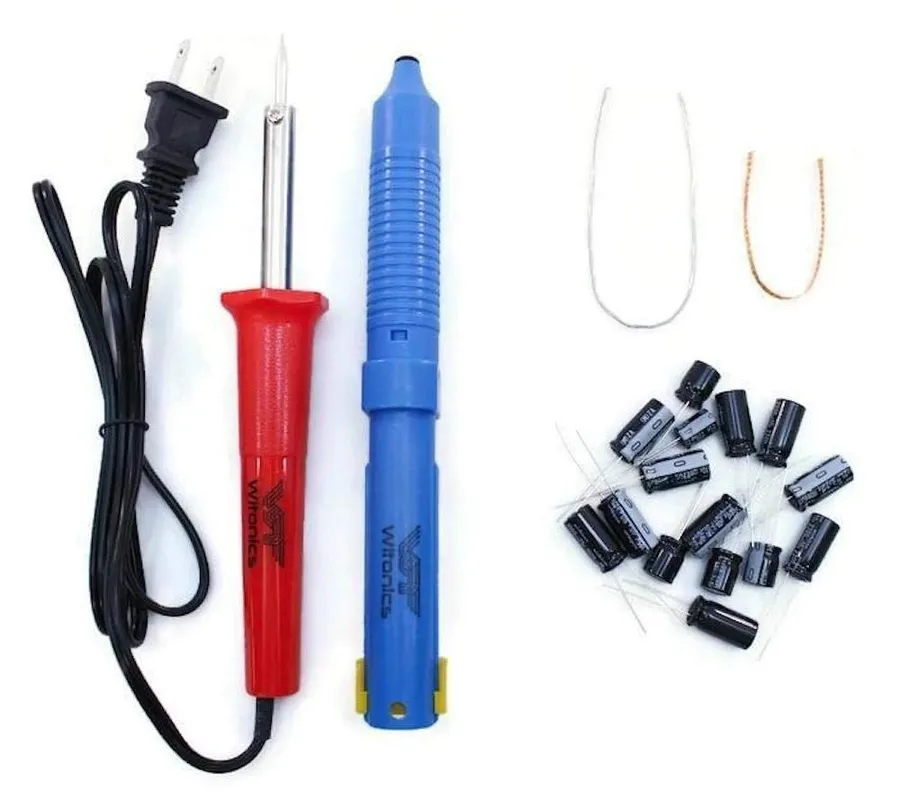
Soldering Capacitors When soldering capacitors, avoid prolonged heat exposure, which could damage the capacitor. Use proper soldering techniques and suitable tools to ensure a secure and reliable connection. For surface mount components, use a hot air reflow station for best results.
Proper PCB Mounting Always adhere to the manufacture specification for mounting on a PCB, this can include things like the space between the component and the board, and the type of solder used.
Mastering capacitor conversions, particularly between 10nF to uF, is essential for anyone working with electronics. By understanding the relationships between farads, microfarads, and nanofarads, and using the correct conversion techniques, you can ensure accuracy in your designs and repairs. With the practical examples and tools provided, you are now well-equipped to navigate the world of capacitor values, enhance your understanding of electronics, and make informed decisions when building and troubleshooting circuits. Remember, consistent practice and a keen eye for detail will take you far in this field.