From adjusting the volume on our old stereos to fine-tuning complex industrial equipment, potentiometers have long been essential components. In today's digital age, the electronic potentiometer, also known as a digital potentiometer or 'digipot', has emerged as a versatile and precise alternative to its mechanical counterparts. This article explores the world of electronic potentiometers, elucidating their function, types, and applications while examining the differences that set them apart from traditional potentiometers.
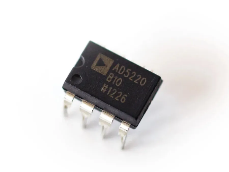
An electronic potentiometer, often called a digital potentiometer or digipot, is a digitally controlled variable resistor. Unlike traditional mechanical potentiometers that are adjusted manually, a digipot's resistance is altered electronically through digital signals. This electronic control allows for precise, repeatable adjustments and seamless integration into digital circuits, mimicking the function of a standard analog potentiometer but with enhanced capabilities.
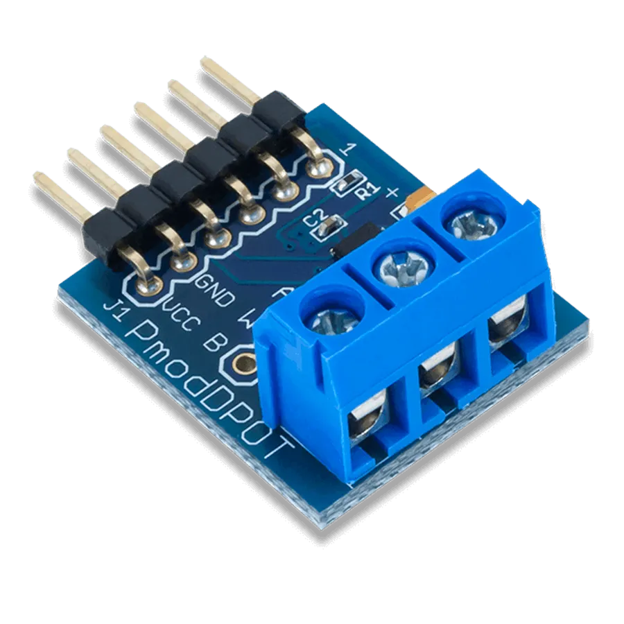
Electronic potentiometers, also known as digital potentiometers or digipots, are categorized primarily by their data retention characteristics: volatile and non-volatile. This distinction is crucial as it affects how they behave when power is removed and reapplied. Understanding these differences is key to selecting the appropriate device for a given application.
| Feature | Volatile Digital Potentiometers | Non-Volatile Digital Potentiometers |
|---|---|---|
| Data Retention | Resistance settings are lost when power is removed. Upon restart, they typically revert to a default state (often a pre-defined minimum or maximum resistance). | Resistance settings are preserved even when power is removed. They retain their last set resistance values, allowing for consistent operation upon restart. |
| Internal Structure | Typically simpler circuitry without built-in memory. | Incorporate non-volatile memory (like EEPROM) to store the wiper position. |
| Cost | Generally less expensive due to their simpler design. | Typically more expensive due to the added complexity and non-volatile memory. |
| Application | Suitable for applications where initial states or frequent resets are acceptable, or where the system reconfigures resistance each power-up. | Ideal for applications requiring persistence of settings such as calibration or adjustments that should not be lost during power cycles. |
| Example | Common in basic signal conditioning circuits or temporary adjustments. | Frequently used in industrial settings, programmable analog gain control or applications where consistent settings across power cycles are crucial. |
Beyond the volatile vs non-volatile distinction, other categorizations exist based on interface type (SPI, I2C), resolution (number of taps or increments), maximum current and voltage and physical packaging. However, the data retention property remains a critical factor in determining suitability to various applications.
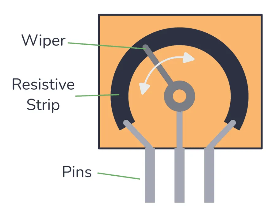
Electronic potentiometers, often called digipots, achieve variable resistance through a digitally controlled network of resistors and electronic switches. Unlike their mechanical counterparts which rely on physical movement, digipots use digital signals to change the resistance, enabling precise electronic adjustments.
At the heart of a digipot is a resistor ladder network, constructed from a series of fixed-value resistors. Electronic switches, typically MOSFETs, are strategically placed within this network. A digital control circuit, responding to commands from a microcontroller or other digital device, activates these switches. By selectively closing different switches, different segments of the resistor ladder are included in the circuit, effectively altering the overall resistance.
The control of these switches is typically achieved via communication protocols, with SPI (Serial Peripheral Interface) and I2C (Inter-Integrated Circuit) being common choices. These protocols allow microcontrollers to send commands to the digipot, specifying the desired resistance setting. The microcontroller transmits a digital code, which corresponds to a specific configuration of the electronic switches within the digipot.
| Component | Function | Description |
|---|---|---|
| Resistor Ladder | Provides discrete resistance steps | A series of fixed resistors that determine the range of resistance achievable by the digipot. |
| Electronic Switches (MOSFETs) | Select specific resistance paths | Act as digital gates to include or exclude sections of the resistor ladder. Controlled by a digital signal. |
| Digital Control Circuit | Interprets digital commands | Decodes incoming digital signals (e.g., via SPI or I2C) from a microcontroller to determine which switches to activate. |
| Communication Protocol | Enables digipot control | Standardized method of data exchange between the microcontroller and the digipot, (e.g. SPI and I2C). |
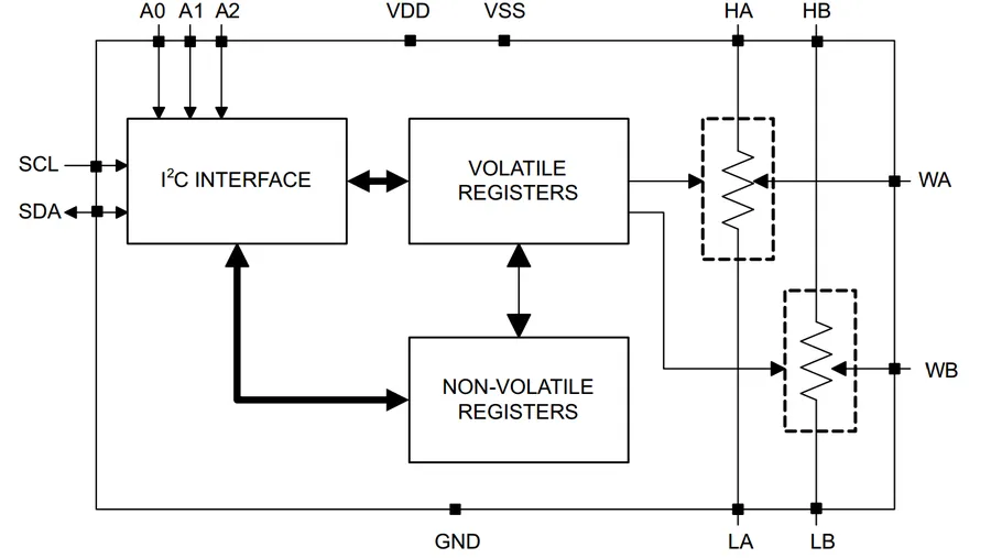
Electronic potentiometers, also known as digital potentiometers or digipots, offer a significant departure from traditional mechanical potentiometers in terms of control, precision, and integration with digital systems. While both achieve the same basic function of variable resistance, their operational mechanisms and characteristics differ considerably, leading to distinct advantages and limitations.
| Feature | Mechanical Potentiometer | Electronic Potentiometer (Digipot) |
|---|---|---|
| Control Mechanism | Manual rotation of a shaft or slider | Digital signals through a microcontroller or other digital circuit |
| Precision | Limited by mechanical tolerances and manual adjustment | High precision, often controlled with step-like increments based on digital resolution |
| Lifespan | Subject to wear and tear, contact degradation, and mechanical fatigue | Solid-state construction; no moving parts, hence a significantly longer lifespan |
| Adjustment | Manual and prone to backlash and limited repeatability | Precise and repeatable adjustments through digital commands |
| Integration | Direct, analog circuit integration | Seamless integration with digital circuits; compatible with microcontrollers |
| Susceptibility to Wear | High wear due to mechanical parts. | No mechanical wear, leading to increased reliability |
| Remote Control | Not feasible without external mechanical linkages. | Easy to control remotely, which allows for automation. |
| Noise | Potentially noisy operation due to wiper contact | Reduced noise since it is a solid-state device |
| Resistance Stability | Resistance can change due to wear, temperature variation or contact problems. | Resistance is much more stable over time and environmental changes. |
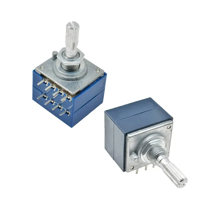
Electronic potentiometers, or digipots, find extensive application across diverse fields due to their precise digital control and adaptability. Their ability to mimic analog potentiometers while offering digital interface advantages makes them indispensable in modern electronic systems. From fine-tuning audio signals to complex industrial automation, digipots provide a versatile solution for variable resistance requirements.
| Application | Use Case Example | Specific Electronic Potentiometer Type |
|---|---|---|
| Audio Control | Digital volume control in an amplifier | MCP4017 |
| Lighting Control | LED dimming circuit | AD5206 |
| Sensor Calibration | Calibrating a pressure sensor | DS1844 |
| Industrial Automation | Motor speed control in a conveyor belt | MAX5420 |
| Power Control | Adjusting bias voltage in an amplifier circuit | MAX5405 |
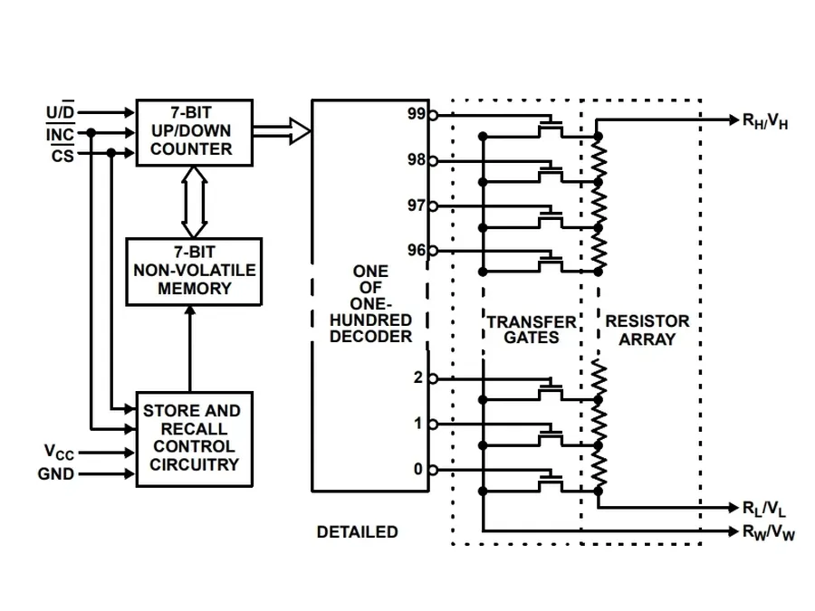
Electronic potentiometers, also known as digital potentiometers or digipots, offer numerous advantages over their mechanical counterparts, making them a preferred choice in many modern electronic applications. Their core strength lies in their ability to provide digitally controlled variable resistance, enabling precise adjustments and seamless integration with digital control systems.
Electronic potentiometers, or digipots, are versatile components in modern electronics, offering digitally controlled variable resistance. This section addresses common questions about their use, purpose, and types, providing clarity for both beginners and experienced users.
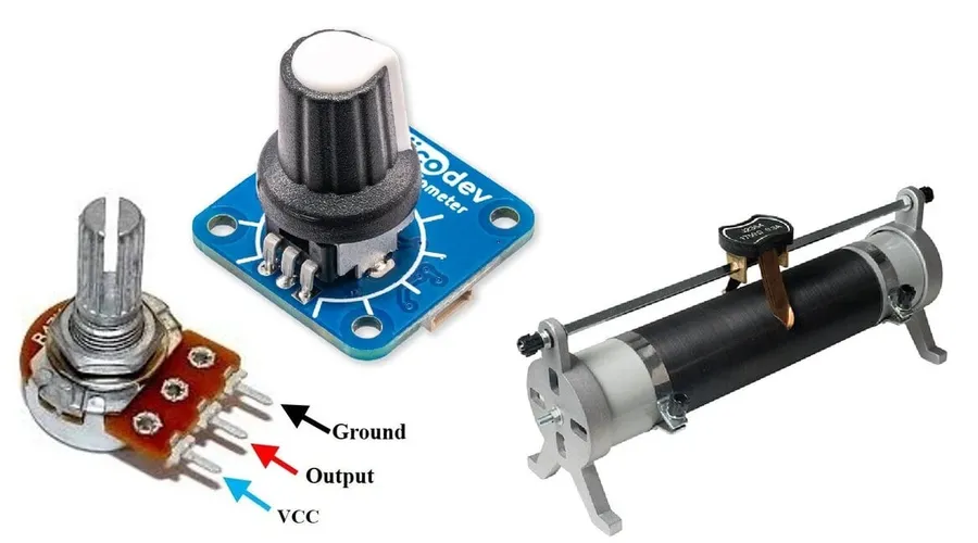
Selecting the appropriate electronic potentiometer, or digipot, is crucial for optimal performance in any given application. This decision hinges on a number of critical factors that must align with the specific requirements of your circuit design and operational needs. Understanding these factors allows for the selection of a device that will provide the required functionality and reliability without over-engineering the solution.
| Factor | Description | Considerations |
|---|---|---|
| Resistance Range | The total resistance that the potentiometer can provide, from the lowest to highest value. | Ensure the selected range covers the required operational resistance for your application. A too-narrow range may not suffice, while a too-broad range may lead to reduced resolution at the needed values. |
| Resolution | The smallest incremental change in resistance that can be achieved. This is usually specified in terms of number of taps or bits. | High-resolution digipots allow for finer adjustments. Determine the level of precision needed for your application to achieve smooth and accurate results. For instance, audio volume control may require finer resolution than say, temperature setting. |
| Voltage and Current Limits | The maximum voltage and current the digipot can safely handle without damage. | Exceeding these limits can damage the component, potentially leading to circuit failure. Consider the voltage and current requirements of your circuit when selecting a digipot. |
| Communication Protocol | The method by which the digipot communicates with a microcontroller or other controlling device (e.g., SPI, I2C). | Choose a protocol that is compatible with your microcontroller. The availability of libraries and ease of implementation can vary based on the chosen communication method. |
| Accuracy | The degree to which the actual resistance value matches the commanded or intended value. | High accuracy is paramount in applications where precise control is essential, such as calibration circuits or precise sensor adjustments. |
| Volatility | Whether the digipot retains its resistance value when power is removed. | Volatile digipots require re-setting on power-up, while non-volatile types retain their values. Consider whether the device's state needs to be maintained across power cycles. |
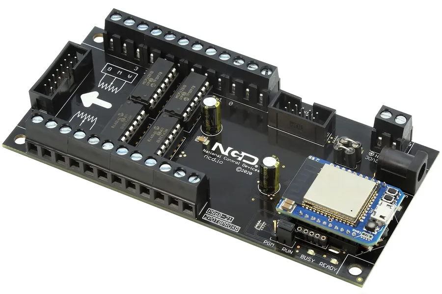
Interfacing electronic potentiometers, often referred to as digipots, with microcontrollers unlocks a wide array of possibilities for precise and dynamic resistance control. This section will explore the methods and protocols for integrating these components, focusing on practical aspects relevant to embedded systems development.
Microcontrollers interact with digipots primarily through digital communication interfaces like SPI (Serial Peripheral Interface) and I2C (Inter-Integrated Circuit). These interfaces enable the microcontroller to send commands to the digipot, instructing it to adjust its resistance setting.
The selection between SPI and I2C typically depends on the number of devices on the bus, speed requirements, and the specific digipot's interface. SPI is usually faster but requires more pins per device, while I2C uses fewer pins but has a lower speed.
For controlling a digital potentiometer, you'll need to consult the datasheet of your specific digipot to understand the required command sequences. These sequences are usually structured as bytes or words that contain address and command data to adjust the wiper position (and therefore resistance) according to the desired setpoint. The microcontroller sends these sequences through the SPI or I2C lines.
Below is an example of basic communication protocol with the digipot:
# Example of setting a digipot using SPI (Simplified)

def set_digipot_spi(spi_bus, chip_select_pin, resistance_value):
    spi_bus.activate_chip_select(chip_select_pin)
    command_byte = get_command_byte(resistance_value)  # Function to create command byte
    spi_bus.transfer(command_byte)
    spi_bus.deactivate_chip_select(chip_select_pin)

# Example of setting a digipot using I2C (Simplified)

def set_digipot_i2c(i2c_bus, device_address, resistance_value):
    command_byte = get_command_byte(resistance_value)  # Function to create command byte
    i2c_bus.send_byte(device_address, command_byte)
Specific libraries and hardware solutions often simplify the interface process. For example:
Controlling digipots effectively requires a good understanding of their command structure and of the specific communication protocols. With the appropriate setup, microcontrollers provide a versatile and robust method to precisely control digipot resistance.
Electronic potentiometers have revolutionized how we adjust and control resistance in electronic circuits. Their precision, reliability, and integration with digital systems have made them indispensable in modern electronics. As technology advances, the importance of the electronic potentiometer will only continue to grow, opening new doors for innovation and automation across various industries. Whether you are an electronics hobbyist or an industrial engineer, understanding the capabilities of digipots is crucial for staying at the forefront of technology.

