Just as a water hose has a nozzle to control flow, an ohm resistor manages the flow of electricity. It's a fundamental electronic component, vital to countless devices we use daily. This guide unpacks the intricacies of ohm resistors, their role in circuits, how to identify them using color codes, and their relationship with Ohm's Law, offering a comprehensive understanding that bridges the gap from basic concepts to real-world applications, ensuring you grasp not just what they are, but why they are indispensable.
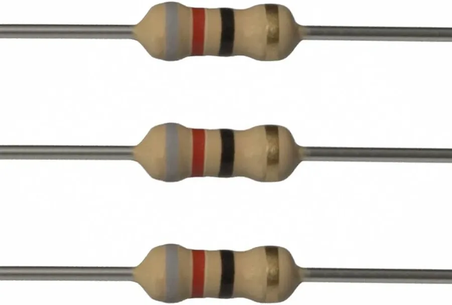
An ohm resistor is a fundamental passive electronic component designed to introduce a specific amount of electrical resistance into a circuit, effectively impeding the flow of electrical current. This resistance is measured in ohms (Ω), named after Georg Ohm, the discoverer of Ohm's Law.
The primary function of an ohm resistor is to limit current flow, control voltage levels, or provide a voltage drop within a circuit. By controlling these parameters, ohm resistors play a critical role in managing the behavior of electronic circuits, ensuring they operate as intended and preventing damage from excessive current or voltage. The construction and composition of a resistor directly impacts its stability, precision, and temperature coefficient, making the selection of the correct type and rating essential for each application.
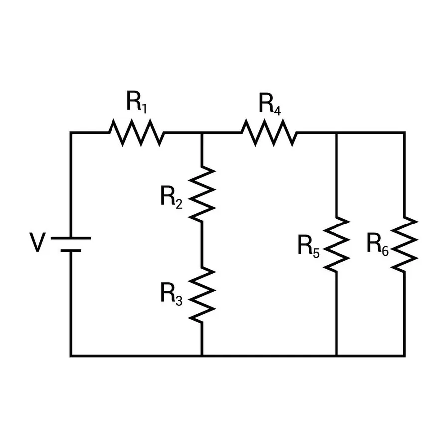
Electrical resistance is a fundamental property that opposes the flow of electric current within a material, quantified by the unit 'ohm' (Ω). This opposition arises from the collisions between charge carriers (usually electrons) and the atoms of the material they traverse. Understanding resistance, measured in ohms, is crucial for designing and analyzing electrical circuits, as it directly influences how current flows in response to an applied voltage.
The ohm, symbolized by the Greek letter Omega (Ω), is defined as the resistance between two points of a conductor when a constant potential difference of one volt, applied to these points, produces in the conductor a current of one ampere. This is formally expressed through Ohm's Law, which establishes a proportional relationship between voltage, current and resistance.
| Parameter | Symbol | Unit | Description |
|---|---|---|---|
| Resistance | R | Ohm (Ω) | Opposition to current flow. |
| Voltage | V | Volt (V) | Electrical potential difference. |
| Current | I | Ampere (A) | Flow of electrical charge. |
The relationship between voltage (V), current (I), and resistance (R) is described by Ohm's Law: V = IR. This equation underscores that for a constant voltage, higher resistance results in lower current and vice-versa. A material's resistance depends on its inherent properties (resistivity), length, and cross-sectional area; longer and thinner materials exhibit greater resistance.
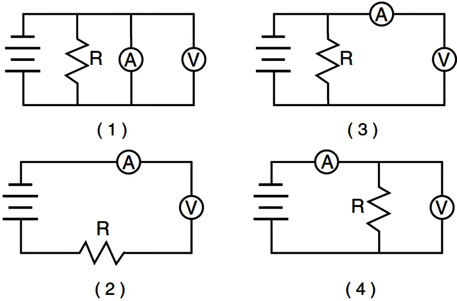
Ohm's Law is a foundational principle in electrical engineering, describing the relationship between voltage, current, and resistance in an electrical circuit. This law is expressed mathematically as V = IR, where V represents voltage (measured in volts), I represents current (measured in amperes), and R represents resistance (measured in ohms). Understanding and applying Ohm's Law is crucial for both analyzing existing circuits and designing new ones.
The core of Ohm's law lies in the linear relationship that exists between voltage and current for many materials and components, particularly at fixed temperatures. This means if you double the voltage across a resistor, you will also double the current flowing through it, provided the resistance remains constant. This linear behavior is characteristic of what is known as an Ohmic material.
Ohm's Law can be rearranged to solve for different variables as required:
It's important to note that Ohm's Law has limitations and does not apply to all circuit components, or under all conditions. For example, some semiconductor devices exhibit non-linear behavior and do not follow Ohm's Law directly. Furthermore, the temperature of a component can alter its resistance, influencing the way Ohm's Law applies in real-world scenarios. Despite these limitations, Ohm's Law provides a valuable, fundamental model for understanding and working with electrical circuits.
| Variable | Symbol | Unit | Description |
|---|---|---|---|
| Voltage | V | Volt (V) | Electrical potential difference. |
| Current | I | Ampere (A) | Rate of electrical charge flow. |
| Resistance | R | Ohm (Ω) | Opposition to current flow. |
Consider a simple circuit consisting of a 9V battery connected to a 100-ohm resistor. Using Ohm's Law:
# Given:
Voltage = 9 # V
Resistance = 100 # ohms

# Calculating Current
Current = Voltage / Resistance
print(Current)
# The result of this calculation is Current = 0.09 Ampere, or 90mA
This basic example illustrates how Ohm’s Law can be applied to calculate current in a simple circuit with known voltage and resistance values.
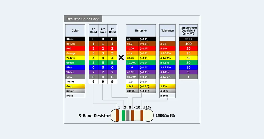
Resistor color codes provide a standardized method for quickly identifying the resistance value and tolerance of a resistor. These color bands, painted on the body of the resistor, offer a straightforward way to determine its specifications without the need for electronic testing in many situations.
| Color | Digit | Multiplier | Tolerance (%) |
|---|---|---|---|
| Black | 0 | 1 | N/A |
| Brown | 1 | 10 | 1 |
| Red | 2 | 100 | 2 |
| Orange | 3 | 1,000 | N/A |
| Yellow | 4 | 10,000 | N/A |
| Green | 5 | 100,000 | 0.5 |
| Blue | 6 | 1,000,000 | 0.25 |
| Violet | 7 | 10,000,000 | 0.1 |
| Grey | 8 | N/A | 0.05 |
| White | 9 | N/A | N/A |
| Gold | N/A | 0.1 | 5 |
| Silver | N/A | 0.01 | 10 |
| None | N/A | N/A | 20 |
Most resistors use either four or five color bands. In a four-band resistor, the first two bands represent the first two digits of the resistance value, the third band represents the multiplier, and the fourth band indicates the tolerance. Five-band resistors add a third digit to the resistance value by using three bands for the resistance value itself, before the multiplier and tolerance band. It's critical to note that reading the resistor code is done from left to right. The tolerance band is often set slightly apart from the other bands.
For example, a resistor with the bands Brown, Black, Red, and Gold would be interpreted as follows: Brown (1), Black (0), Red (multiplier of 100), and Gold (5% tolerance). Therefore, the resistance is 10 x 100 = 1000 ohms or 1kΩ with a tolerance of ±5%. The 5-band resistor with bands of Brown, Black, Black, Brown and Gold would be interpreted as 100 ohms and multiplied by 10 (brown) so the final value is 1000 ohms or 1kΩ with a tolerance of ±5%.
Understanding resistor color codes is essential for anyone working with electronics as it enables quick identification and use of components, and this skill is fundamental in assembling, repairing, and designing electronic circuits. Always ensure to double-check the code on a resistor, and to use tools such as a multimeter to verify the value if there is a possibility of misreading the band, or if the band is damaged and difficult to identify.
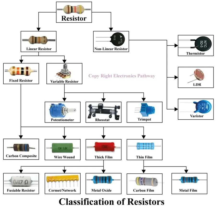
Ohm resistors, fundamental components in electronic circuits, are manufactured in a variety of types, each with distinct characteristics and applications. These variations arise from differences in construction materials and manufacturing processes, resulting in a range of electrical properties and suitability for diverse applications. Understanding these distinctions is critical for selecting the appropriate resistor for a given circuit design.
| Resistor Type | Material | Characteristics | Typical Applications | Power Rating | Temperature Coefficient |
|---|---|---|---|---|---|
| Carbon Film | Carbon film deposited on a ceramic substrate | Cost-effective, general purpose, moderate tolerance | General electronics, low-power circuits | Low to Medium | Moderate |
| Metal Film | Thin metal film deposited on a ceramic substrate | High precision, low noise, good stability | Precision electronics, audio equipment, instrumentation | Low to Medium | Low |
| Wire-Wound | Metal wire wound around a ceramic or fiberglass core | High power, good precision, can have high inductance | Power supplies, motor control, high current applications | Medium to High | Low |
| Surface Mount (SMD) | Various resistive materials in small packages | Compact size, suitable for automated assembly, various characteristics | Modern electronics, portable devices, high density circuits | Low | Variable |
Key parameters in selecting resistors include power rating, which indicates the maximum power the resistor can dissipate without damage, and temperature coefficient, which describes how the resistance changes with temperature. Proper consideration of these factors ensures reliable performance of the electronic circuit. Different types of resistors exhibit specific trade-offs between accuracy, stability, cost, and suitability for particular uses.
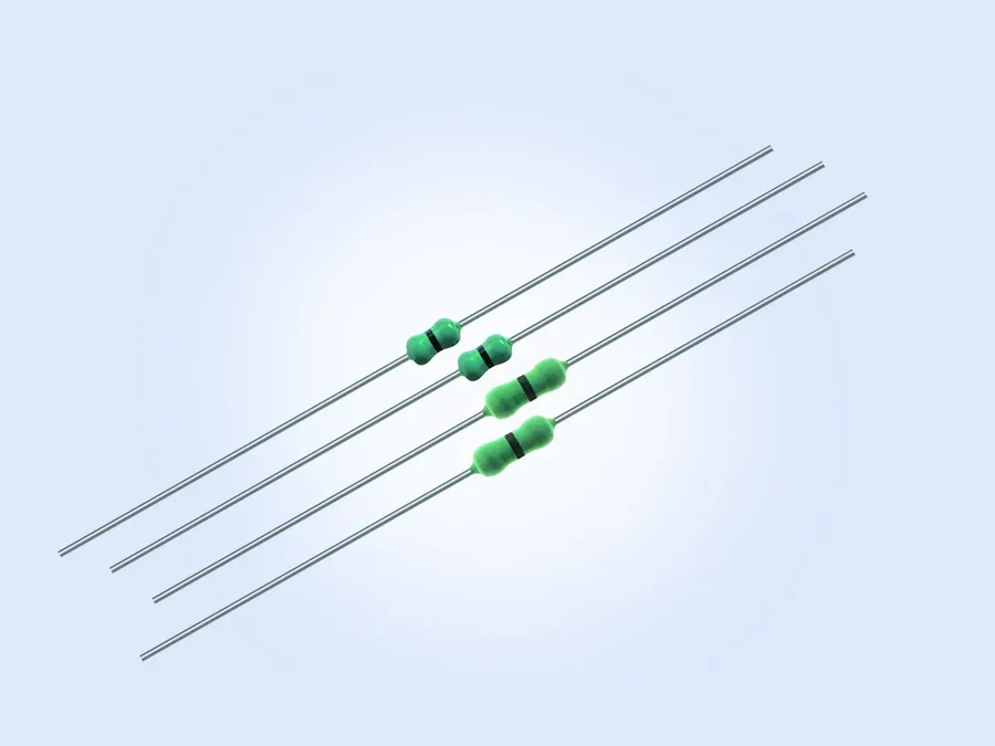
Zero-ohm resistors, often appearing counterintuitive, are not actually resistors in the conventional sense but rather function as links or jumpers on a printed circuit board (PCB). Their primary purpose is to provide a direct electrical connection with minimal impedance, acting as a substitute for a wire trace. They offer manufacturing and design advantages over simply using a direct copper trace.
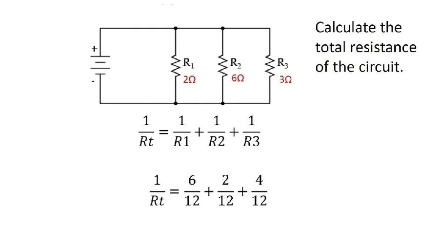
Understanding how resistors behave in series and parallel configurations is crucial for designing and analyzing electronic circuits. These configurations affect the overall resistance, current flow, and voltage distribution within the circuit, requiring precise calculations for desired functionality.
In a series circuit, resistors are connected end-to-end, forming a single path for current flow. The total resistance in a series circuit is simply the sum of all individual resistances.
| Configuration | Formula for Total Resistance | Current | Voltage |
|---|---|---|---|
| Series | R_total = R1 + R2 + ... + Rn | Same through each resistor | Divides across resistors |
| Parallel | 1/R_total = 1/R1 + 1/R2 + ... + 1/Rn | Divides through each resistor | Same across each resistor |
In a parallel circuit, resistors are connected side-by-side, creating multiple paths for current flow. The reciprocal of the total resistance is equal to the sum of the reciprocals of individual resistances.
Here's a breakdown of how to calculate total resistance and understand their effects:
It is important to note that the formulas provided are applicable when dealing with resistors in ideal conditions. In practical scenarios, factors like resistor tolerances, temperature coefficients, and parasitic effects may impact the actual circuit behavior. Always consider these parameters when designing electronic circuits.
This section addresses common questions about ohm resistors, clarifying their uses, values, and impacts in electronic circuits. By answering these frequently asked questions, we aim to provide a solid understanding of how ohm resistors function in various applications.

Ohm resistors, fundamental components in electronic circuits, are ubiquitously found across a wide spectrum of applications. They serve the primary function of limiting current flow, ensuring that other circuit components operate within their safe parameters. Their presence is not limited to simple circuits but extends into complex systems.
Below are several examples where ohm resistors play crucial roles, ranging from simple analog circuits to sophisticated digital systems:
The selection of appropriate resistor values and types is crucial for each application to ensure that the components function correctly and safely. Failure to do so may result in circuit malfunctions or component failure. Precise consideration of resistance, power rating, tolerance, and temperature coefficient is needed for any electronic design.
In summary, the seemingly simple ohm resistor is a cornerstone of modern electronics. Understanding its properties, from resistance values determined by color codes to its behaviour governed by Ohm's Law, empowers anyone to effectively design and troubleshoot circuits. Whether you are a student, hobbyist, or professional, mastering ohm resistors provides the building blocks for creating a wide array of electronic devices and systems. We encourage you to further explore this fundamental component and how it helps control electricity, essential for the operation of countless everyday technologies.

