Mylar Capacitor: Unveiling Its Versatility and Applications
2025.02.01
From the intricate circuits in our smartphones to the power grids that light our cities, electronic components like the mylar capacitor are essential. Often called polyester capacitors, these components are like tiny energy reservoirs, storing and releasing electrical charge. Understanding their role, characteristics and comparisons can help both hobbyists and professionals. In this article, we'll unravel the inner workings of mylar capacitors, their applications, and how they fit into the world of electronics, offering a practical guide to these frequently encountered components.
What is a Mylar Capacitor?
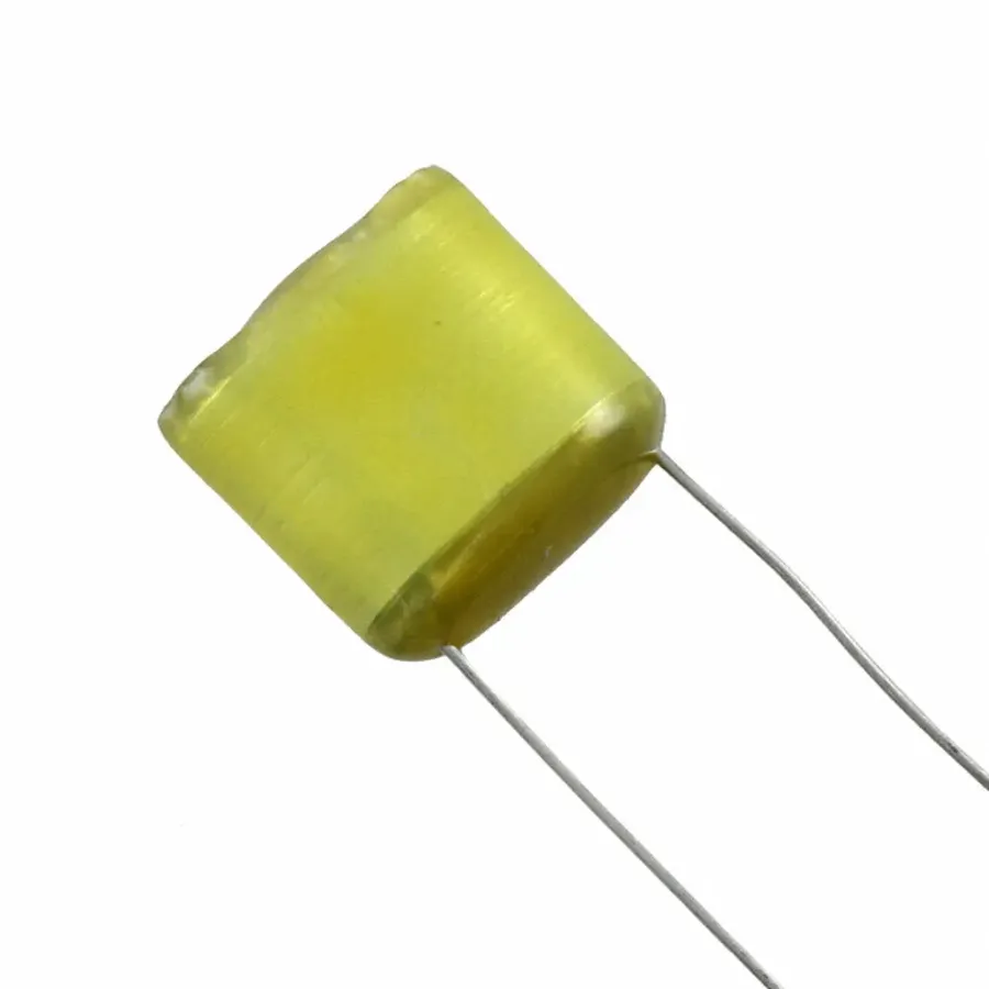
Mylar Film Capacitor
A Mylar capacitor, also commonly referred to as a polyester capacitor, is a type of capacitor that employs a thin film of Mylar, a brand of biaxially-oriented polyethylene terephthalate (BoPET), as its dielectric material. This dielectric is sandwiched between two conductive plates, usually made of metalized material such as aluminum. The capacitor stores electrical charge by accumulating electrons on these plates, separated by the non-conductive Mylar film, and releases this energy when needed within an electronic circuit. This construction gives Mylar capacitors unique properties making them suitable for a variety of applications.
Key Characteristics of Mylar Capacitors
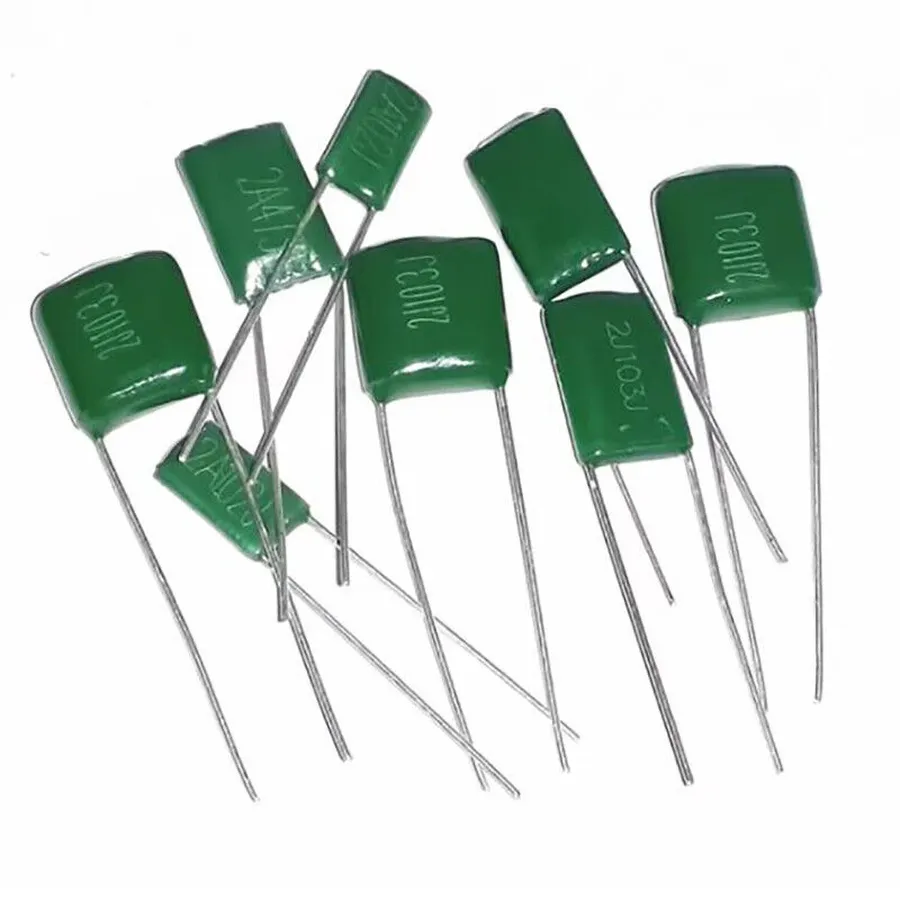
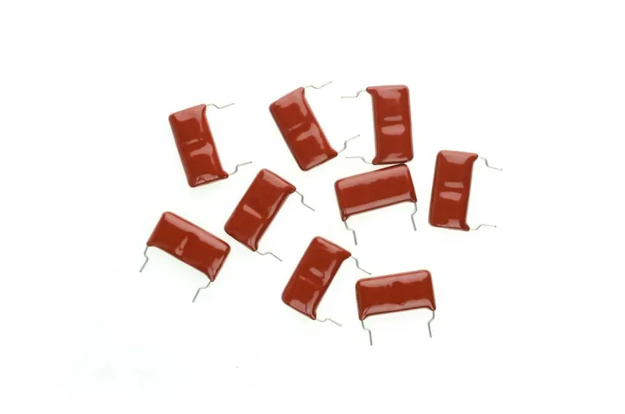
Various Mylar Capacitors
Mylar capacitors, also known as polyester film capacitors, are characterized by their stable electrical properties, making them suitable for a wide range of applications. Their key characteristics, including capacitance range, voltage ratings, temperature tolerance, and dissipation factor, dictate their performance and suitability for various electronic circuits. Understanding these parameters is critical for engineers and hobbyists alike in selecting the correct component.
Characteristic
Typical Range
Description
Capacitance
1 pF to 47 µF
The amount of charge the capacitor can store; available in a wide range for diverse applications.
Voltage Rating
50V to 630V or higher
Maximum voltage the capacitor can withstand without failure; suitable for low to medium voltage circuits.
Temperature Tolerance
-55°C to 125°C
The operating temperature range; known for good stability within these limits, ensuring reliable performance in varying conditions.
Dissipation Factor (DF)
0.001 to 0.01
Measure of energy loss in the capacitor; usually low, indicating minimal power dissipation.
Tolerance
±1% to ±10%
The precision of the actual capacitance value relative to the marked value. Tighter tolerances are available for more demanding applications.
Insulation Resistance
Typically > 10^12 ohms
A measure of how well the capacitor blocks current; extremely high in Mylar Capacitors
Mylar Capacitor Applications
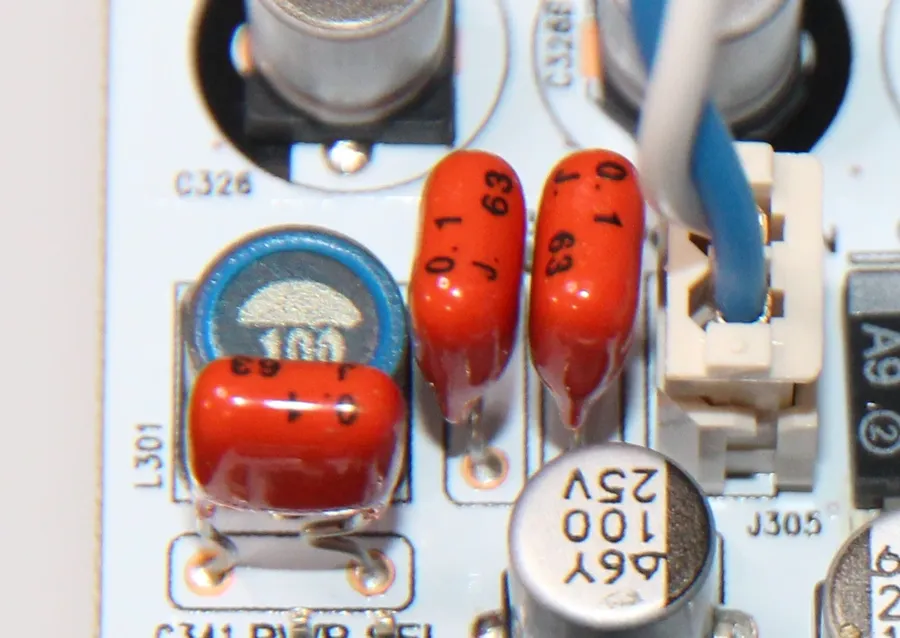
Mylar Capacitor on PCB
Mylar capacitors, known for their stable performance and reliable operation, find widespread use in a variety of electronic applications. Their unique electrical properties make them suitable for both general-purpose and specialized tasks. These applications leverage their precise capacitance, low dissipation factor, and good temperature stability.
Timing Circuits Mylar capacitors are frequently used in timing circuits because of their consistent capacitance over time and temperature. They are crucial in applications such as oscillators, pulse generators, and other timing-sensitive electronics.
Filtering Circuits In filtering applications, mylar capacitors are ideal for smoothing out voltage or current fluctuations in electronic circuits. Their low dissipation factor and minimal dielectric absorption result in efficient signal processing, making them great for both low-pass and high-pass filters.
Coupling and Decoupling Circuits Mylar capacitors are employed in coupling applications to transfer AC signals from one circuit to another while blocking DC components. They also serve as decoupling capacitors, providing a local reservoir of charge to prevent voltage dips in power rails and enhance the signal integrity of circuits.
Audio Applications Their low distortion characteristics and temperature stability make mylar capacitors excellent for audio circuitry, where the accurate reproduction of sound signals is vital. They can be found in amplifiers, equalizers, and other audio processing units where high-fidelity is a key requirement.
Power Applications Mylar capacitors are also used in some power applications, particularly those requiring moderate voltage and current handling. Although not used for high power systems like electrolytic capacitors, they are used in some switching circuits and power converters, where their stable electrical characteristics are valued.
Mylar vs. Ceramic Capacitors: A Detailed Comparison
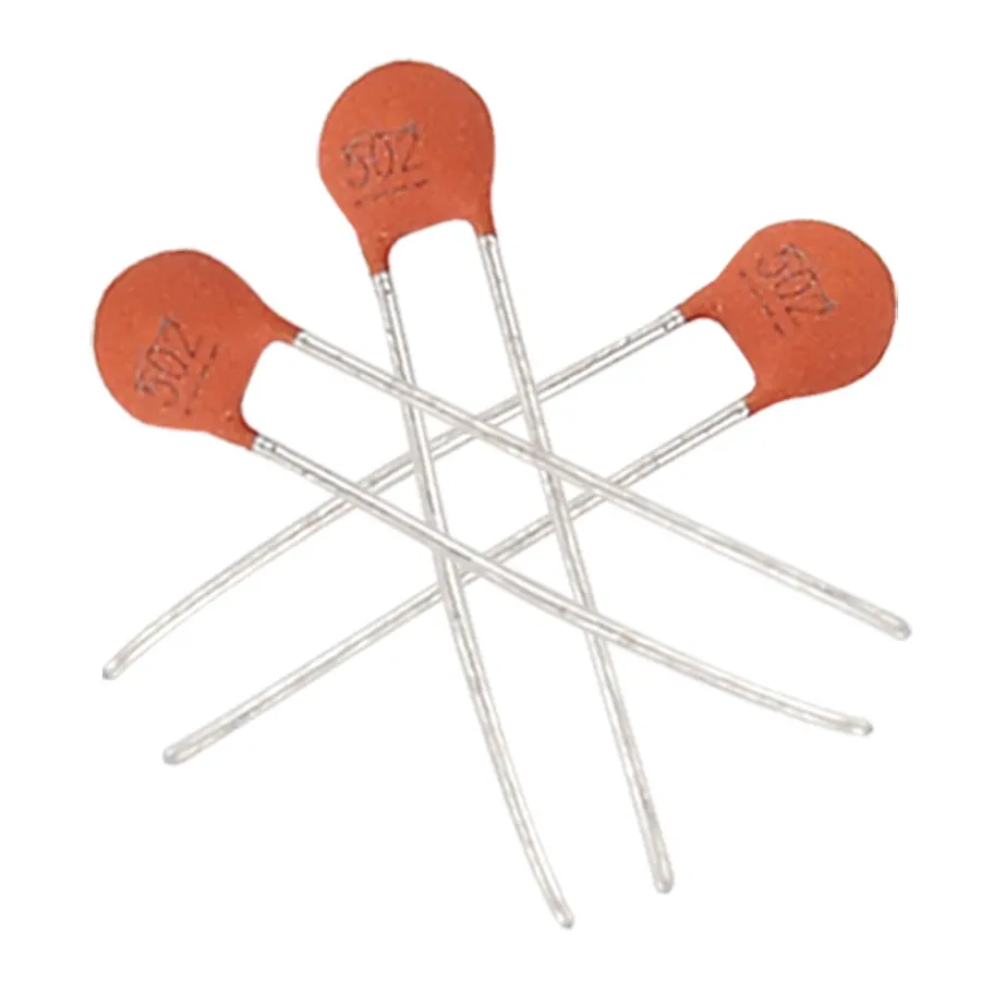
Mylar vs Ceramic Capacitors
Mylar and ceramic capacitors represent two prevalent capacitor types, each with distinct characteristics that make them suitable for specific applications. Understanding their differences is crucial for selecting the appropriate component in electronic circuit design. This section provides a comprehensive side-by-side comparison, focusing on their performance, cost, and ideal use cases.
Characteristic
Mylar Capacitor
Ceramic Capacitor
Capacitance Range
Generally 1 pF to 47 µF
Typically 1 pF to 100 µF or higher
Voltage Rating
50V to 630V and higher
Generally 10V to several kV, varies significantly by type
Temperature Coefficient
Relatively stable, lower temp coefficient than ceramic
Can vary significantly, often with a higher temperature coefficient
Tolerance
Generally tighter, 5-10% or better
Wider range, 5-20% or worse depending on type
Dissipation Factor
Lower, good for high frequency applications
Higher, less suitable for high frequency applications
Mylar vs. Electrolytic Capacitors: When to Use Each
Mylar vs Electrolytic Capacitors
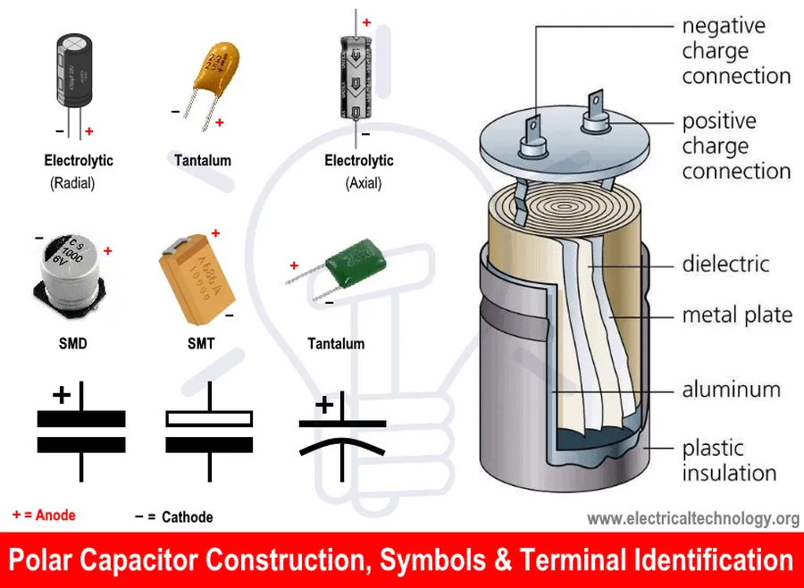
Mylar and electrolytic capacitors serve distinct roles in electronic circuits, primarily due to their differing construction, electrical characteristics, and resulting performance. Understanding these differences is crucial for selecting the appropriate capacitor for a specific application. Mylar capacitors, known for their stability and non-polarity, contrast sharply with electrolytic capacitors, which offer high capacitance in a compact form but come with polarity and limitations on operating frequencies and temperature.
Feature
Mylar Capacitor
Electrolytic Capacitor
Capacitance Range
Generally lower, typically from a few picofarads to a few microfarads
Generally higher, ranging from microfarads to farads
Polarity
Non-polar
Polar (must be connected correctly)
Voltage Rating
Moderate to high, from tens to hundreds of volts
Wide range, from a few volts to hundreds of volts
Temperature Tolerance
Good, typically -55°C to 125°C
Limited, typically -40°C to 105°C (depending on type)
Frequency Response
Excellent, suitable for high-frequency applications
Limited, typically used in low-frequency applications
Equivalent Series Resistance (ESR)
Low
Higher, especially at higher frequencies
Lifespan
Long lifespan, stable over time
Finite lifespan, performance degrades over time, especially with temperature
Power supplies, smoothing, bypass capacitors, energy storage
The choice between mylar and electrolytic capacitors depends heavily on the application's specific requirements. Mylar capacitors excel in applications where stability, low losses, and good high-frequency performance are critical. Examples include precision timing circuits, audio signal processing, and filtering applications. In contrast, electrolytic capacitors are the go-to choice where high capacitance is required in a small package, such as power supply smoothing and decoupling in lower frequency circuits. However, their inherent polarity and limitations at higher frequencies make them unsuitable for many applications where mylar capacitors would perform well.
Mylar Capacitor Codes: Deciphering the Numbers
Mylar capacitors, like many electronic components, utilize a coded system to convey their electrical characteristics. These codes, often printed directly on the capacitor's body, provide essential information about capacitance, tolerance, and voltage rating. Understanding these codes is crucial for selecting the correct capacitor for a given application and ensuring circuit functionality.
The coding system is not standardized across all manufacturers, but there are common conventions that are widely used. Typically, these codes can be broken down into numeric and alphanumeric representations, often using a combination of methods to represent the capacitor’s characteristics.
Here's a breakdown of how to interpret these codes:
Capacitance Value: The capacitance is usually indicated by a three-digit number. The first two digits are significant figures, and the third digit represents the multiplier (i.e., the number of zeros to add). For example, '103' means 10 x 10^3 pF, or 10,000 pF (10 nF). A code like '472' corresponds to 4700pF (4.7nF).
Tolerance: Tolerance is indicated by a letter code, which specifies how much the actual value might deviate from the stated value. Common codes are: J (±5%), K (±10%), and M (±20%).
Voltage Rating: The voltage rating is often explicitly given in volts (V) or represented by a letter code (rare). It’s critical that the capacitor's voltage rating exceeds the maximum voltage in your circuit to prevent damage or failure. Sometimes, the voltage is coded, but most of the time it is stated directly in volts.
Additional Codes: Some capacitors include additional codes that specify temperature coefficient, working temperature range, or manufacturer-specific data. If not explicitly noted, these codes can be assumed to follow industry standards.
Code
Capacitance (pF)
Tolerance
Interpretation
102J
1000
±5%
10 x 10^2 pF, 5% tolerance
473K
47000
±10%
47 x 10^3 pF, 10% tolerance
104M
100000
±20%
10 x 10^4 pF, 20% tolerance
225J
2200000
±5%
22 x 10^5 pF, 5% tolerance
Frequently Asked Questions About Mylar Capacitors
This section addresses common questions about mylar capacitors, clarifying their applications, comparing them to other capacitor types, and assessing their reliability. Understanding these aspects is crucial for selecting the correct component for specific electronic circuit designs.
What are the primary applications of Mylar capacitors? Mylar capacitors, known for their stability and reliability, are widely used in timing circuits, filters, coupling and decoupling applications. Their versatility extends to both audio circuits, for signal processing, and power electronics, where they are valued for their high voltage and temperature tolerance. They are a solid choice where consistent performance over a wide range of conditions is needed.
What distinguishes Mylar capacitors from ceramic capacitors? Mylar capacitors and ceramic capacitors differ significantly in their construction, performance, and applications. Mylar capacitors typically offer better stability with temperature variations and higher voltage ratings, making them suitable for high-voltage and high-temperature conditions. Ceramic capacitors, on the other hand, usually feature smaller size and higher frequency capabilities, making them ideal for high-frequency applications. Mylar capacitors are generally preferred in audio and analog circuits, while ceramic capacitors are often found in digital circuits.
Are Mylar capacitors a good choice for general use? Mylar capacitors are considered a very good choice for general applications where stable and reliable performance is needed. They are less prone to failure than electrolytic capacitors and offer a cost effective solution for many low to medium frequency applications. They excel in applications where high stability over time and temperature is needed, and can tolerate high voltages, making them more robust than ceramic capacitors in certain cases. Their reliability and good electrical properties mean they offer an excellent balance of performance and cost.
How do Mylar capacitors compare with polyester film capacitors? Mylar is a specific brand name of polyester film made by DuPont. The terms are often used interchangeably. Both types of capacitors share very similar electrical characteristics and applications. The key material used is polyethylene terephthalate (PET), hence both Mylar and polyester capacitors have very similar properties, which means they often can be used as direct replacements for each other.
Can Mylar capacitors be used in high-frequency applications? While Mylar capacitors do have some high-frequency capabilities, they are generally not the ideal choice for very high-frequency applications. Their performance may degrade at higher frequencies, and other types of capacitors, such as ceramic capacitors, are often preferred for such use cases. Mylar capacitors are more suited to low to medium-frequency applications that require stability and reliability.
What are the typical failure modes of Mylar capacitors? Mylar capacitors are relatively robust and do not suffer from polarized failure modes. However, they can fail if they are exposed to voltages or temperatures exceeding their ratings. Over time, the dielectric material can degrade, leading to a loss in capacitance or an increase in the dissipation factor. These types of failures usually occur gradually over the life of the product rather than catastrophic failure.
How should Mylar capacitors be stored to maintain their performance? To maintain the performance of Mylar capacitors, they should be stored in a dry environment at room temperature and avoid exposure to high humidity and direct sunlight. Keeping them in their original packaging before use can provide additional protection against environmental factors that may degrade their performance. They do not have any specific storage requirements other than the typical standards for any electronic components.
Practical Tips for Using Mylar Capacitors
Mylar Capacitor Application
Proper handling, soldering, and storage are crucial for maintaining the performance and longevity of mylar capacitors. These practical tips ensure their effective integration into electronic circuits, preventing damage and ensuring reliability.
Handling Mylar Capacitors Avoid applying excessive mechanical stress or bending the leads of mylar capacitors, as this can damage the internal structure, particularly the thin dielectric film. When handling, use clean, dry tools and avoid direct contact with the capacitor body to prevent contamination from oils and salts from skin.
Soldering Mylar Capacitors Apply minimal heat during soldering to prevent heat damage to the capacitor. Use a temperature-controlled soldering iron and limit exposure to high temperatures. Prolonged exposure to heat can alter the capacitor's characteristics. Ensure leads are properly and securely soldered to prevent open circuit issues. Avoid cold solder joints, which can lead to intermittent failures. Use proper soldering techniques to minimize thermal stress.
Storage of Mylar Capacitors Store mylar capacitors in a dry, controlled environment with stable temperature to prevent moisture ingress, which can lead to degradation of the insulation and changes in capacitance value. Avoid storing capacitors in environments with extreme temperatures. Store them away from direct sunlight and chemicals that may react with or degrade the materials, particularly the outer coating.
Selecting the Right Capacitor Always verify the capacitor specifications such as capacitance, voltage rating, and temperature tolerance, as these values are critical to the circuit's performance and can affect the circuit's intended functionality. Before selecting a capacitor, always refer to the circuit design specifications and select capacitors that meet the requirements.
Circuit Board Placement Place the capacitor in a location on the board that minimizes the risk of mechanical damage or thermal stress from other components on the PCB. It is important to consider the proximity to heat generating components such as power transistors. Consider the airflow and ventilation when placing the components.
Regular Inspections Regular visual inspections during the assembly process and during routine maintenance can reveal damaged or defective capacitors that should be replaced. Look for any discoloration, cracks or deformation of the capacitor body as well as loose or corroded leads.
Future Trends in Mylar Capacitor Technology
The evolution of mylar capacitor technology, while not as rapid as some other areas of electronics, is still showing promising developments. Future trends focus on enhancing performance characteristics, miniaturization, and exploring new materials to improve overall efficiency and reliability in increasingly demanding applications.
Miniaturization and Increased Volumetric Efficiency A key trend is the push towards smaller form factors without sacrificing capacitance or voltage ratings. This involves advancements in manufacturing processes and material science to pack more performance into less space.
Improved Temperature Stability Research is ongoing to develop mylar capacitors that exhibit less capacitance variation over a wider temperature range. This is critical for reliable performance in harsh environments or applications with temperature fluctuations.
Enhanced High-Frequency Performance Ongoing research is exploring ways to minimize parasitic inductance and resistance in mylar capacitors, to extend their use into higher-frequency circuits. This involves innovative electrode designs and internal structures.
Development of New Dielectric Materials While mylar (polyester) has been a workhorse material, research into alternative dielectric films is ongoing. This could lead to enhanced performance in terms of higher temperature tolerance, lower dielectric losses, and higher voltage capabilities.
Integration with Advanced Packaging Techniques Future mylar capacitors are expected to be integrated more easily with advanced packaging techniques such as surface-mount technology (SMT), minimizing assembly time and cost.
Sustainable and Eco-Friendly Production There is an increasing focus on using more environmentally friendly materials and manufacturing processes. This involves finding sustainable alternatives to current materials and reducing waste in production.
Mylar capacitors, a versatile electronic component, stand out for their reliability, stability and flexibility in diverse applications. Their ability to store and release electrical energy within specific parameters makes them indispensable in various fields of electronics. This article aimed to provide a comprehensive understanding of mylar capacitor’s workings, applications, and comparisons with other types, ensuring that readers are well-equipped to make informed decisions when incorporating them into electronic designs. As technology continues to advance, mylar capacitors will continue to play a crucial role, adapting to the ever-changing demands of the industry.