From everyday electronics to complex industrial machinery, diodes play a crucial role. Among them, the SS14 diode stands out for its efficiency as a Schottky rectifier. This article will delve into the intricacies of the SS14, exploring its working principles, applications, and what makes it a cornerstone component in modern circuits, bridging the gap between fundamental technology and its practical applications.
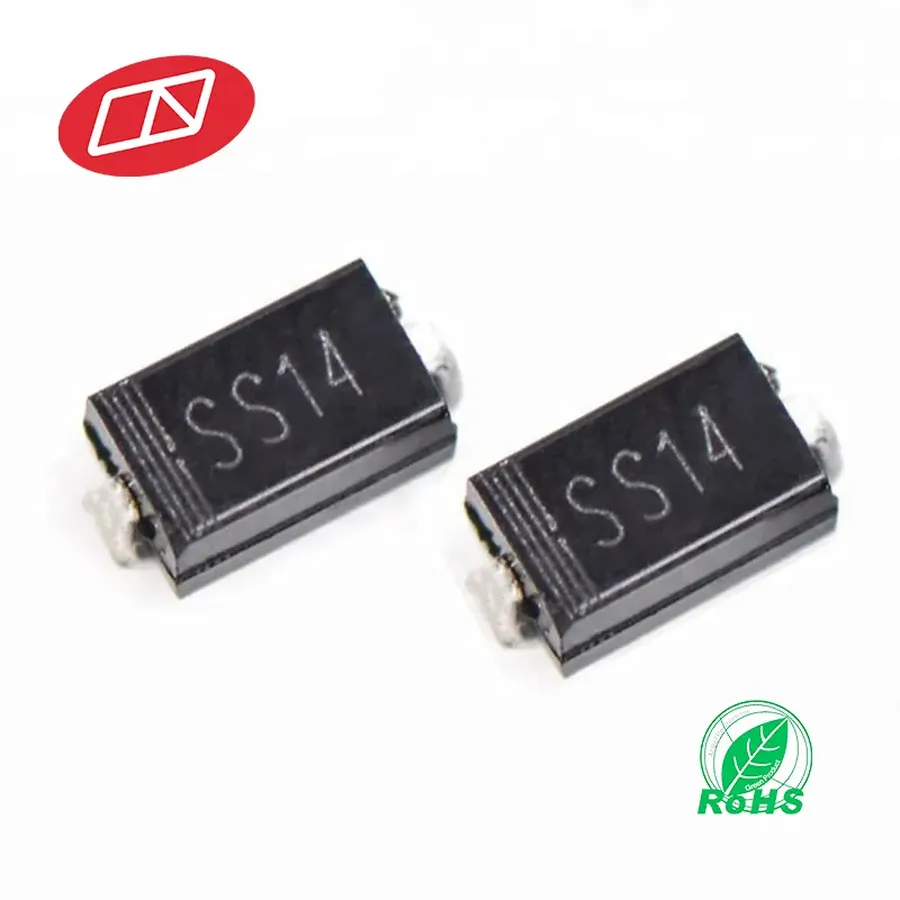
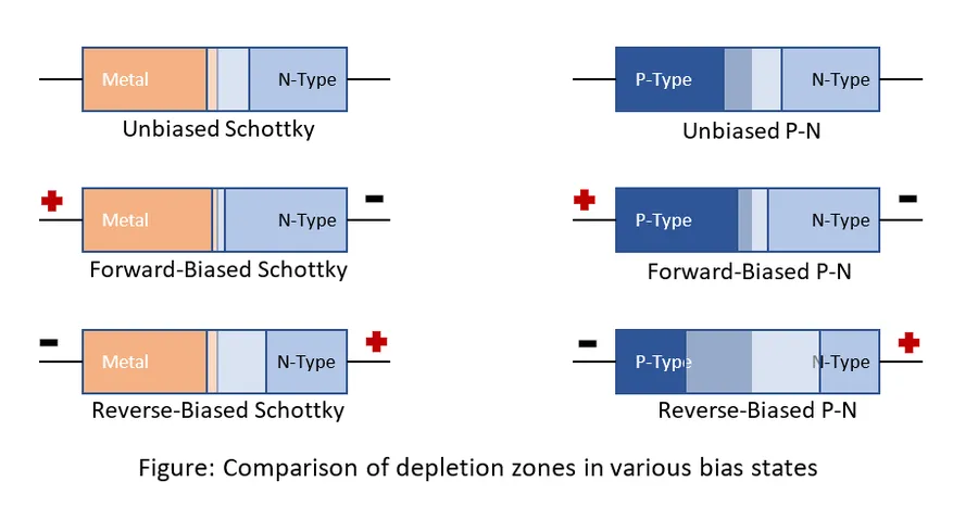
The SS14 is a surface-mount Schottky Barrier Rectifier diode, characterized by its low forward voltage drop and rapid switching speed. These attributes make it highly efficient in various electronic applications. It leverages a metal-semiconductor junction, rather than a traditional p-n junction, facilitating its low forward voltage drop compared to traditional diodes. The SS14 diode is typically constructed using a metal-semiconductor junction, such as a metal (like aluminum) in contact with an N-type semiconductor (typically silicon). When a forward voltage is applied, electrons from the semiconductor can readily flow into the metal, while the Schottky barrier prevents the reverse current flow.
The SS14 Schottky diode is characterized by specific electrical parameters crucial for circuit design and performance. These parameters include forward voltage drop, reverse voltage, current rating, and its physical packaging, typically an SMA/DO-214AC surface-mount package. Understanding these specifications is essential for proper application of the SS14 diode.
| Parameter | Typical Value | Unit | Description |
|---|---|---|---|
| Maximum Repetitive Peak Reverse Voltage | 40 | V | The maximum voltage that can be applied in reverse periodically without causing breakdown. |
| Maximum Average Forward Rectified Current | 1.0 | A | The maximum current the diode can handle continuously in the forward direction. |
| Maximum Peak Forward Surge Current | 40 | A | The maximum current the diode can withstand for a short period (typically one cycle). |
| Forward Voltage Drop (at 1A) | 0.55 | V | The voltage drop across the diode when a forward current of 1A is flowing. Note that it will vary depending on the forward current. |
| Operating Junction Temperature | -55 to +125 | °C | The range of temperatures in which the device will operate properly. |
| Package Type | SMA (DO-214AC) | - | The physical package of the diode, surface mount. |
It is important to note that these values can slightly vary between manufacturers. Therefore, always consult the specific datasheet from the chosen vendor for precise parameter values. The typical forward voltage drop is around 0.55 V at 1A, a crucial characteristic contributing to its high efficiency as a rectifier or in other applications.
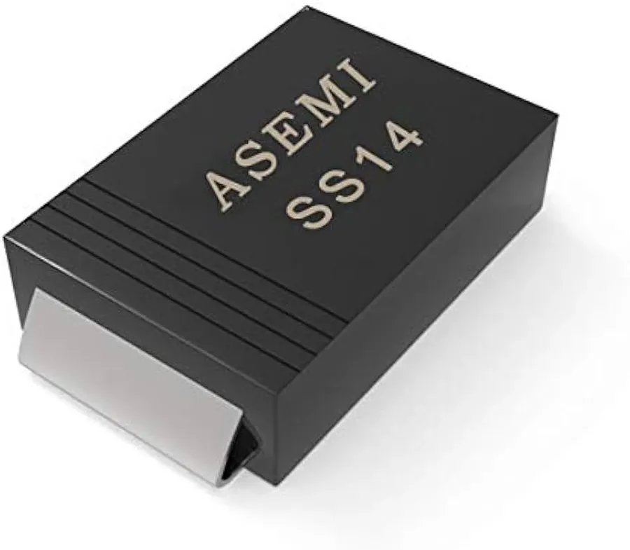
The SS14 Schottky diode distinguishes itself through a combination of performance-enhancing attributes, making it a preferred component in various electronic applications. Its key features, including low forward voltage drop, high efficiency, minimal power losses, over-voltage protection capabilities, and suitability for automated assembly processes, underscore its value in modern circuit designs.
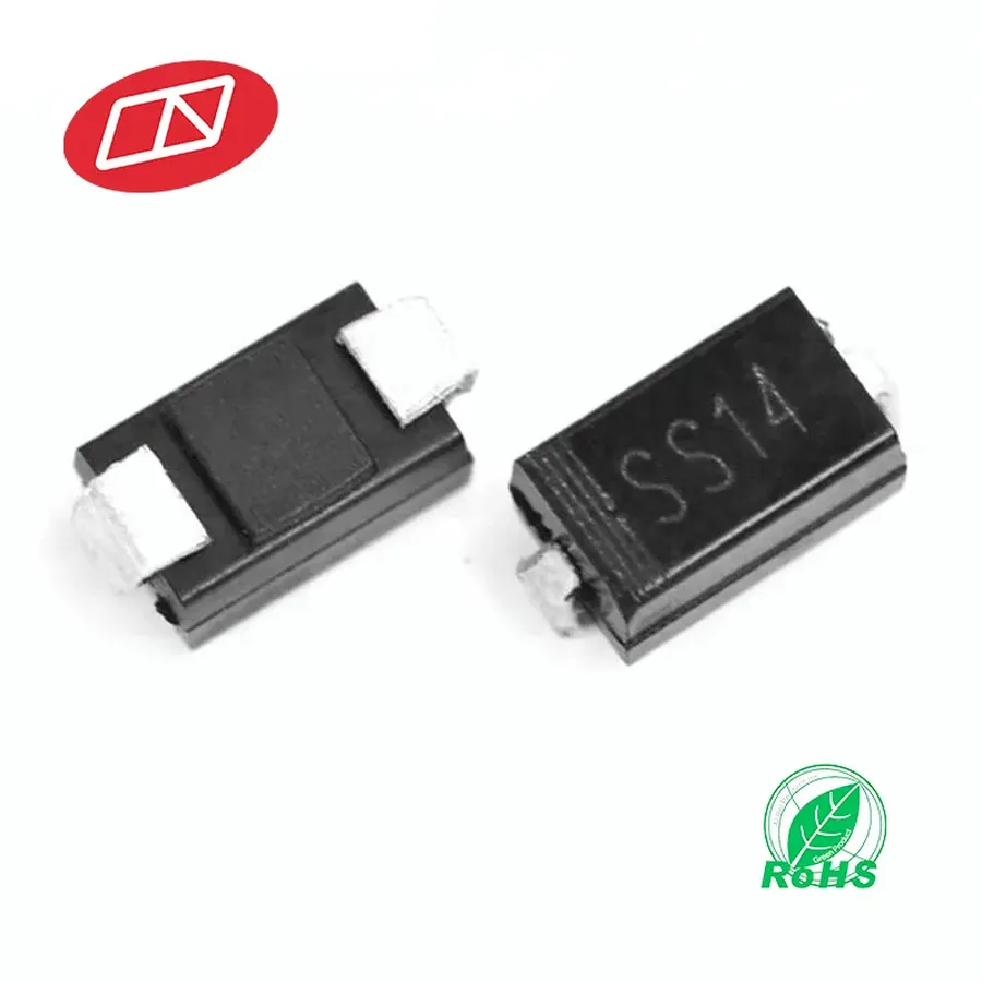
The SS14 Schottky diode's unique characteristics, notably its low forward voltage drop and high switching speed, make it a versatile component across numerous electronic applications. Its efficiency in minimizing power loss and its rapid response to changing current demands are critical in many circuits. This section details several key application areas where the SS14 diode is commonly utilized.
The SS14 Schottky diode stands out for its specific performance characteristics, but understanding how it compares to other Schottky diodes is crucial for optimal circuit design. This section provides a comparative analysis of the SS14 with similar diodes, including the SS12, SS13, SS16, and 1N5819, highlighting key differences in their electrical parameters. We will also address the common confusion between the SS14 and SS34 diodes.
| Parameter | SS12 | SS13 | SS14 | SS16 | 1N5819 |
|---|---|---|---|---|---|
| Maximum Average Forward Current (A) | 1.0 | 1.0 | 1.0 | 1.0 | 1.0 |
| Maximum Peak Reverse Voltage (V) | 20 | 30 | 40 | 60 | 40 |
| Typical Forward Voltage Drop (V) at 1A | 0.38 - 0.55 | 0.4 - 0.58 | 0.45 - 0.6 | 0.47 - 0.65 | 0.45 - 0.6 |
| Package Type | SMA/DO-214AC | SMA/DO-214AC | SMA/DO-214AC | SMA/DO-214AC | DO-41 |
The table above illustrates that while all these diodes are in the 1A current range, their key difference lies in the reverse voltage capabilities. For example, the SS12 has the lowest reverse voltage rating at 20V, making it suitable for lower-voltage applications, while SS16 can handle up to 60V, suited for more demanding voltage requirements. The forward voltage drop varies slightly among these diodes, which is an important consideration for power efficiency in switching applications. Additionally, the 1N5819, while similar in voltage and current ratings, comes in a different package (DO-41) which can influence physical integration in designs.
A common point of confusion arises between the SS14 and SS34 diodes. While both are Schottky diodes with similar physical packages (SMA/DO-214AC), their main difference is in their maximum reverse voltage rating. The SS14 has a maximum reverse voltage rating of 40V, whereas the SS34 is rated for 30V. This difference is a critical factor when selecting a diode based on specific voltage requirements of the circuit. Users need to check the manufacturer datasheet for exact values to ensure they select the right component for the intended application.
Testing an SS14 Schottky diode is crucial to ensure its proper functionality within a circuit. This section provides a practical guide on how to use a multimeter for testing and outlines basic troubleshooting steps when issues arise.
Before testing an SS14 diode, it's imperative to understand that Schottky diodes, including the SS14, exhibit a lower forward voltage drop than standard silicon diodes. This characteristic is key to interpreting test results accurately. Moreover, diodes should ideally be tested out of circuit to avoid interference from other components. However, in-circuit testing can still provide valuable diagnostic information with some caveats.
Always observe safety precautions when working with electronic circuits, especially when using a multimeter to avoid short circuits and potential damage to the device under test or measuring equipment.
Selecting an appropriate equivalent or replacement for the SS14 Schottky diode requires careful consideration of its key electrical parameters and physical package. This ensures seamless integration into existing circuits and maintains the desired performance characteristics. Critical parameters include forward voltage drop (Vf), reverse voltage (Vr), forward current (If), and the physical package (SMA/DO-214AC).
A suitable replacement for the SS14 diode must match or exceed its specifications. For instance, a higher current rating (If) can be used, but a lower one should not, as it may lead to component failure. Similarly, the reverse voltage (Vr) rating of the replacement must be equal to or greater than that of the SS14 to avoid breakdown under reverse bias conditions. The forward voltage drop (Vf) should ideally be equal to or lower than the SS14 for efficiency. The package should match to fit into the existing PCB footprint.
When searching for equivalents, it is crucial to consult datasheets from different manufacturers to identify components with comparable specifications. It is also important to consider the operating environment (temperature, humidity, etc.) as it can affect the performance and reliability of the replacement component.
| Parameter | SS14 | Equivalent Considerations |
|---|---|---|
| Forward Voltage Drop (Vf) | ~0.5V (at 1A) | Equal to or lower |
| Reverse Voltage (Vr) | 40V | Equal to or higher |
| Forward Current (If) | 1A | Equal to or higher |
| Package Type | SMA/DO-214AC | Must match |
Common equivalents can be found among other Schottky diodes within the same series from various manufacturers. For example, an SS16, which has a similar package and a slightly higher reverse voltage and current rating, could be considered if a safety margin is needed. Components from brands like Vishay, ON Semiconductor, and Diodes Incorporated offer potential SS14 alternatives.
This section addresses common queries about the SS14 diode, offering concise answers to enhance understanding of its functionality and applications. These FAQs are designed to provide quick and clear information regarding the SS14 diode and its related topics.
In conclusion, the SS14 diode is a highly efficient and versatile component essential in modern electronics, specifically as a Schottky rectifier. With its low forward voltage drop, high current capacity, and overvoltage protection, the SS14 diode exemplifies the progress in semiconductor technology. Whether you are designing a new circuit or troubleshooting an existing one, understanding the functionality of the SS14 diode and its equivalents is crucial. As technology advances, the SS14 and its derivatives will continue to power innovation across many electronic applications.

