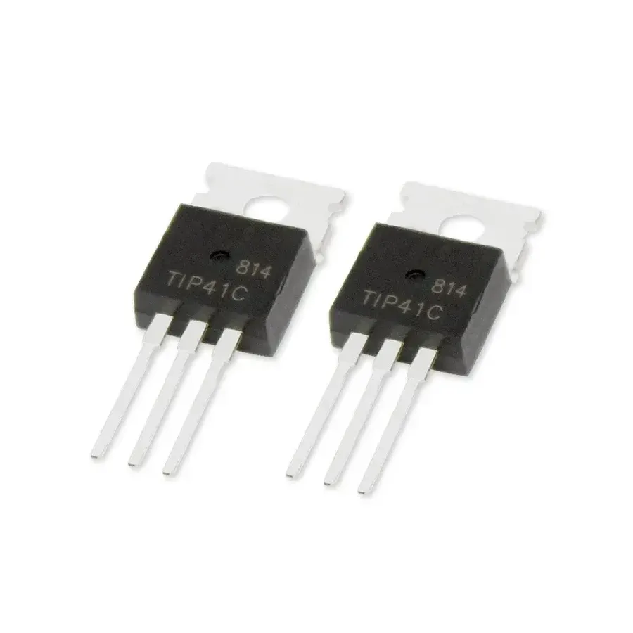
Unlocking the Potential of the TIP41C Transistor: A Comprehensive Guide
2025.01.29
In the world of electronics, the TIP41C transistor is like a reliable workhorse, powering various circuits with its robust performance. This NPN power transistor is essential for both linear and switching applications, playing a key role in everything from audio amplifiers to power supply regulators. In this article, we will dissect its specifications, explore its diverse uses, and understand why this component continues to be a go-to for many design engineers. We'll dive deep into its capabilities and the technology behind its reliability. Get ready to explore what makes the TIP41C an indispensable part of modern electronics.
Understanding the Basics of the TIP41C Transistor
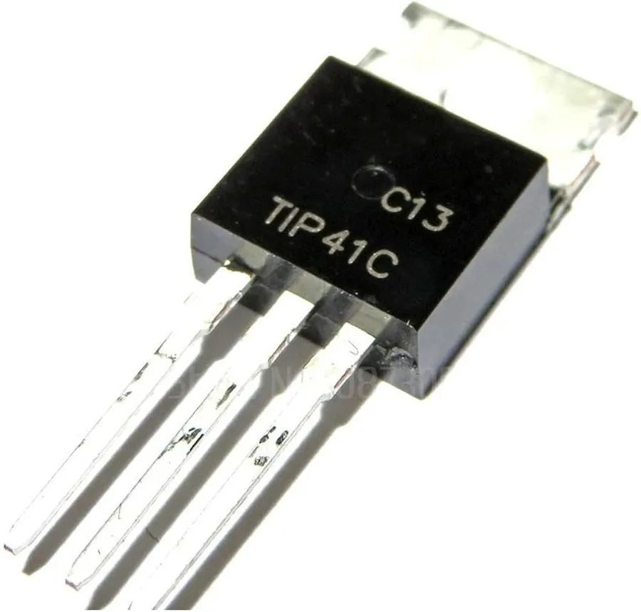
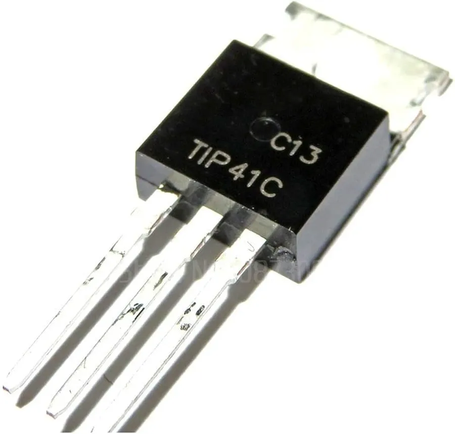
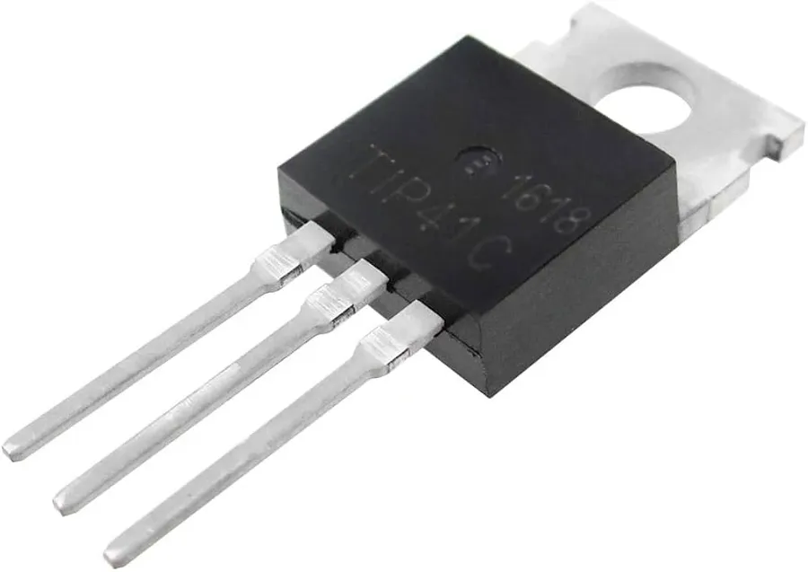
TIP41C Transistor
The TIP41C is a widely used NPN bipolar junction transistor (BJT) that serves as a fundamental building block in many electronic circuits, primarily functioning as an amplifier or a switch for electronic signals. Its construction and characteristics make it suitable for a variety of applications where moderate power handling is required.
At its core, a BJT, like the TIP41C, consists of three semiconductor layers, forming two junctions. In an NPN transistor, a thin p-type layer (the base) is sandwiched between two n-type layers (the collector and emitter). Current flow between the collector and emitter is controlled by a small current applied to the base. When a sufficient base current is present, it allows a larger current to flow from the collector to the emitter. This principle enables the transistor's two fundamental modes of operation: amplification, where the output current is a scaled version of the input current, and switching, where a small base current can control a much larger current between the collector and emitter.
Key Electrical Characteristics of the TIP41C Transistor
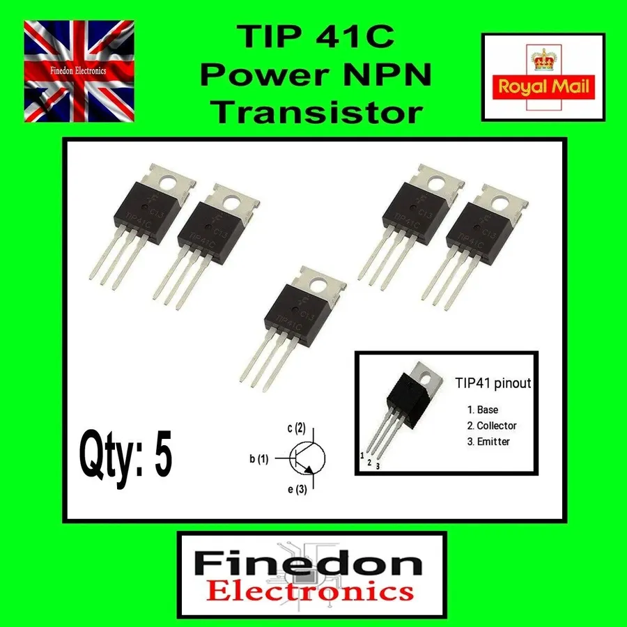
TIP41C Pinout Diagram
The TIP41C, as a NPN bipolar junction transistor (BJT), is defined by several critical electrical parameters that dictate its performance and suitability for various applications. Understanding these parameters is crucial for effective circuit design and reliable operation.
Parameter
Symbol
Typical Value
Description
Impact on Application
Collector-Emitter Voltage
VCEO
100V
Maximum voltage that can be applied between the collector and emitter without causing breakdown, with the base open.
Defines the maximum voltage that the transistor can safely switch or amplify. Exceeding this voltage can cause damage.
Collector Current
IC
6A
Maximum current that can continuously flow through the collector. This is the amount of current the transistor is capable of handling.
Determines how much current the transistor can control and thus the power delivery capabilities of the circuit.
Peak Collector Current
ICM
10A
Maximum current pulse the transistor can handle for a short duration.
Allows for short bursts of higher current, important for handling inrush currents or pulses.
Power Dissipation
PD
65W
Maximum power the transistor can dissipate in the form of heat. This is usually under a specific heatsink temperature.
Defines how much power the transistor can handle without overheating, impacting the transistor's longevity and performance.
DC Current Gain
hFE
15-75
The ratio of collector current (IC) to base current (IB), indicating the transistor's current amplification capability.
Important to ensure proper biasing of the transistor and current control.
Base-Emitter Voltage
VBE
0.7 -1.2V
The voltage required to forward bias the base-emitter junction and allow current flow.
Critical for designing appropriate biasing for transistor to turn on correctly.
These parameters are typically specified at a specific temperature, usually 25°C. It is important to consider these parameters under the expected operating conditions. For instance, the maximum power dissipation decreases as the temperature increases, a factor that must be considered in thermal management.
The hFE, also known as beta (β), is not a constant value and can vary based on collector current and temperature. It's important to refer to the TIP41C datasheet for specific graphs and typical values under different operating conditions. Additionally, it's critical to consider a safety margin when designing the circuit. For example, design the circuit to operate below the absolute maximum ratings of each parameter to prevent potential damage to the transistor.
TIP41C vs. Similar Transistors: A Comparative Analysis
TIP41C and Similar Transistors
The TIP41C, a widely-used NPN bipolar junction transistor, is often compared to other similar power transistors. This section delves into a comparative analysis, highlighting key differences in current, voltage, and power handling capabilities, and provides information on common equivalent transistors. This comparison is essential for selecting the appropriate component for specific applications.
Parameter
TIP41C
TIP41A
TIP41B
2N3055
BD139
Collector-Emitter Voltage (VCEO)
100V
40V
60V
60V
80V
Collector Current (IC)
6A
6A
6A
15A
1.5A
Power Dissipation (PD)
65W
65W
65W
115W
8W
DC Current Gain (hFE)
15-75
15-75
15-75
20-70
40-250
Package
TO-220
TO-220
TO-220
TO-3
TO-220
Key Differences and Considerations: The TIP41 series (TIP41A, TIP41B, and TIP41C) are similar in many respects, differing primarily in their voltage ratings. The TIP41A has the lowest VCEO at 40V, while the TIP41B is rated at 60V, and the TIP41C at 100V. This makes TIP41C suitable for higher voltage applications. The 2N3055 is a higher-power transistor with a higher current handling capacity and power dissipation compared to the TIP41 series, and it comes in a TO-3 package, while the BD139 has lower power and current handling capacity but significantly higher current gain. When choosing a transistor, it's vital to consider the specific voltage and current requirements of your application, the necessary power handling, and the required gain.
Equivalent Transistors: Depending on the specific circuit requirements, several transistors can serve as equivalents to the TIP41C. When selecting an equivalent, it's vital to verify that the replacement's VCEO, IC, and power dissipation are equal to or greater than the original. Additionally, check the pin configuration to ensure correct integration. Some examples of possible equivalents include the TIP41A and TIP41B (for lower voltage applications), or the 2N3055 and BD139 (for applications with different power and gain needs).
Applications of the TIP41C Transistor in Various Circuits
TIP41C in Circuit
The TIP41C transistor, a versatile NPN BJT, finds application in a wide array of electronic circuits. Its ability to amplify and switch makes it suitable for both linear and digital applications, commonly appearing in audio amplification, power regulation, and motor control, due to its robust construction and power handling capabilities.
The following sections describe some common circuits where TIP41C excels:
Audio Amplifiers In audio amplifier circuits, the TIP41C functions as a linear amplifier in class A or class AB configurations. It takes small audio signals and amplifies them, which is critical in audio signal processing. It operates in its linear region, allowing for faithful reproduction of audio signals. The transistor's gain allows weak input signals, such as from a microphone or pre-amplifier stage, to be boosted to a level suitable for driving speakers or further stages of amplification. Proper biasing is essential for achieving optimal amplification.
Power Supply Circuits The TIP41C plays a crucial role in various power supply designs, particularly as a pass transistor in linear regulators. In this context, it controls the amount of current delivered to the load, ensuring a stable output voltage despite variations in input voltage or load current. The transistor operates as a variable resistor, allowing a control loop to adjust its resistance, maintaining a fixed output voltage. This application takes advantage of the transistor's ability to operate in its active region, and the power dissipation must be carefully managed by adding a heatsink.
Motor Controllers In motor control applications, the TIP41C can be used as a switch to control the power delivered to the motor, which is useful in speed control or direction reversal. This is accomplished by toggling the transistor between the saturation and cut-off regions. In Pulse Width Modulation (PWM) applications, the transistor is rapidly switched on and off, and the average power delivered to the motor is adjusted by varying the duty cycle. This efficient form of control provides flexibility and precision in controlling the speed and torque of motors. The power and switching capacity are important in this application.
Switching Regulators The TIP41C is also used in switching regulator circuits, where it operates as a switch to regulate the output voltage efficiently. The transistor is either fully on (saturated) or fully off (cut-off) for minimal power dissipation, maximizing energy efficiency. The transistor will be part of a circuit that includes an inductor and a capacitor, where the switching of the transistor allows the conversion of electrical power from one form to another, such as stepping down or stepping up the voltage. This requires a careful selection of external components and consideration of switching speed.
Designing Circuits with the TIP41C: Practical Considerations
TIP41C with Heatsink
Successfully implementing the TIP41C transistor in circuit designs requires careful attention to its pinout, thermal management, and base current requirements. These considerations are critical for ensuring stable and reliable operation of the transistor within its intended application.
Pinout Configuration The TIP41C is a three-terminal device; these are the base (B), collector (C), and emitter (E). Correct identification and connection of these terminals are essential for proper functioning. Typically, the pinout from left to right, with the flat face facing you, is Base-Collector-Emitter.
Heat Management As a power transistor, the TIP41C dissipates a significant amount of heat, especially when operating at higher currents and voltages. Proper heatsinking is crucial to prevent thermal runaway and damage to the device. This usually requires mounting the transistor to a metal heat sink. The size and type of heatsink depend on the power dissipation expected in the specific application. The datasheet should be consulted to find the thermal resistance values for different case-to-ambient heat transfer options.
Base Current Control The TIP41C, being a bipolar junction transistor, is current-controlled. The base current (IB) determines the collector current (IC). To effectively use the TIP41C as a switch or an amplifier, the base current must be carefully controlled. This is usually accomplished by using a series resistor to limit the base current to a safe value. The base current needs to be enough to saturate the transistor fully when used as a switch, while a smaller, controlled amount is needed for amplifier applications. The required base current is directly correlated with the desired collector current and the transistor's current gain (hFE) as shown in the formula Ic = hFE*Ib. Note that the current gain can vary greatly within the specifications on the datasheet.
Consideration
Description
Implication
Pinout
Base (B), Collector (C), Emitter (E) identification
Incorrect wiring may damage the transistor
Heat Management
Dissipation of thermal energy
Insufficient heatsinking can lead to thermal damage or failure.
Base Current
Control current flowing into the base terminal
Improper base biasing will result in non-optimal performance or damage.
Troubleshooting Common Issues with the TIP41C
Effective troubleshooting of the TIP41C transistor is crucial for ensuring the reliability and longevity of electronic circuits. This section addresses common problems encountered when using the TIP41C, offering practical solutions based on fundamental electrical engineering principles.
The TIP41C, like all BJTs, is susceptible to specific failure modes related to its physical structure, thermal limits, and electrical characteristics. By identifying and addressing these issues, engineers and hobbyists can prevent circuit failures and optimize the performance of their designs.
Overheating Overheating is a frequent cause of TIP41C failure, often stemming from excessive power dissipation. The transistor's power dissipation (PD) rating must not be exceeded. To mitigate this, calculate the power being dissipated by the transistor using P = VCE * IC and ensure it is within the specification and implement adequate heat sinking. Check that the thermal resistance of the heatsink is suitable for the dissipated power.
Transistor Failure A complete failure of a TIP41C transistor can present in several ways: short between two or more terminals, open circuit between two or more terminals, or altered operational characteristics. Check the circuit design with a multimeter, testing to make sure no component has exceeded the operating rating. If the failure cause is hard to identify, a process of elimination is often used, starting with replacing the transistor itself with a known good component, if the system is now operational, the old component is faulty, and can be disregarded.
Incorrect Biasing Incorrect biasing can lead to either saturation or cut-off operation of the transistor and therefore malfunction of the entire circuit. Ensure that the base current is properly calculated and configured. A resistor in series with the base limits base current. If this resistance is too high, the transistor will not function correctly as it will not enter into the active or saturation region. If the resistance is too low, the base current will be too high, potentially causing failure.
Excessive Base Current Driving the base with too much current can cause excessive heat dissipation and transistor failure. Ensure the base current is controlled by a suitable series resistor. The base current (IB) can be calculated using the formula: IB = (Vsource - VBE) / R, where VBE is the base-emitter voltage (typically 0.7V for silicon transistors like the TIP41C) and R is the value of the series resistor. Do not exceed the maximum base current of the transistor.
Secondary Breakdown Secondary breakdown occurs due to thermal runaway effects, usually at higher voltages and currents. The transistor may fail catastrophically. The Safe Operating Area (SOA) curve, available in the device datasheet, must not be exceeded, especially with inductive loads where flyback voltages can be a significant risk.
Frequently Asked Questions About the TIP41C Transistor
This section addresses common inquiries regarding the TIP41C transistor, providing concise and authoritative answers to aid engineers and hobbyists in their understanding and application of this component.
What are the primary applications of the TIP41C transistor? The TIP41C is primarily used as a general-purpose NPN bipolar junction transistor in various applications, including audio amplifiers, power supply circuits, motor controllers, and switching regulators. Its robust design allows it to handle moderate power levels, making it suitable for both amplification and switching purposes.
What transistors can be used as a substitute for the TIP41C? Several transistors can serve as substitutes for the TIP41C, depending on the specific requirements of the circuit. Common alternatives include the TIP41A, TIP41B (lower voltage ratings), and the 2N3055 (higher current and power ratings). When selecting a substitute, ensure that the chosen transistor meets or exceeds the original transistor's voltage, current, and power dissipation specifications. Datasheets should be consulted for detailed comparisons.
What is the maximum power dissipation the TIP41C can handle? The maximum power dissipation (PD) for the TIP41C is typically around 65 watts, assuming the case temperature is maintained at 25°C. However, in practical applications, effective heat sinking is crucial to prevent overheating and ensure reliable operation. Exceeding the maximum power dissipation rating can lead to thermal runaway and permanent damage to the transistor.
What is the maximum collector-emitter voltage (VCEO) of the TIP41C? The maximum collector-emitter voltage (VCEO) for the TIP41C is typically 100 volts. This value indicates the maximum voltage that can be safely applied between the collector and emitter terminals without causing breakdown. Operating the transistor beyond this voltage can result in irreversible damage. Therefore, this parameter is critical when designing power supply or switching applications.
What is the typical DC current gain (hFE) of the TIP41C? The DC current gain (hFE), also known as beta, for the TIP41C typically ranges from 15 to 75. This parameter is a critical aspect of understanding the amplification capabilities of the transistor. It represents the ratio of collector current (IC) to base current (IB). The hFE value can vary depending on operating conditions and device manufacturing tolerances; therefore, design considerations should account for a potential variation within the typical range.
How do you ensure proper heat management for the TIP41C? Proper heat management for the TIP41C is essential to prevent overheating and ensure reliable operation. This typically involves using a heat sink attached to the transistor’s case. The size and type of heat sink depend on the power dissipated by the transistor. Thermal calculations should be performed to determine the appropriate heat sink requirements, and thermal grease should be used to ensure proper heat transfer.
The Future of the TIP41C and Similar Components
While the TIP41C transistor is a mature technology, its robust design and cost-effectiveness ensure its continued relevance in various electronic applications. Despite advancements in semiconductor technology leading to more efficient and compact devices, the TIP41C's simplicity and ease of use keep it as a staple component in many designs, particularly in hobbyist projects, educational settings, and legacy equipment maintenance. Its future, while not necessarily at the cutting edge of new innovations, is secure within its niche.
The long-term outlook for the TIP41C and similar components involves a few key aspects:
Continued Use in Legacy Systems Many older electronic devices rely on the TIP41C and similar transistors. As long as these systems are in operation, the demand for these components will persist. This ensures a steady, albeit not expanding, market for the TIP41C.
Educational and Hobbyist Applications The TIP41C's affordability and ease of use make it ideal for educational purposes and hobbyist projects. It provides a hands-on experience for learners to understand the principles of transistor operation and circuit design. This application sector is likely to keep a moderate demand for the TIP41C.
Cost-Effectiveness in Budget-Conscious Designs For applications where cost is a primary consideration, the TIP41C's simplicity and low cost make it an attractive alternative to more modern, expensive transistors. This factor will maintain its presence in budget-driven projects.
Potential for Niche Applications Despite its age, there may be specialized applications where the TIP41C's unique characteristics, such as specific voltage or current capabilities, will still be required. This could involve specific industrial equipment or legacy automotive applications.
Advancements in Replacement Technologies While the TIP41C will still be relevant, advancements in materials science and semiconductor manufacturing will likely lead to more efficient and versatile replacement options. These newer components may gradually supplant the TIP41C in some applications where its limitations become more prominent.
The TIP41C transistor remains a pivotal component in electronics due to its versatility and reliability in handling both linear and switching power applications. Its robust design makes it suitable for a wide range of circuits, from audio amplification to industrial power control. As technology advances, understanding the fundamentals of transistors like the TIP41C is crucial. It provides a solid foundation for designing more complex systems. Despite newer options in the market, the TIP41C continues to be a trustworthy choice, embodying the core principles of transistor operation.