Mastering Breadboard Electronics: A Comprehensive Guide
2025.01.28
Just like a blank canvas empowers artists, breadboards empower electronics enthusiasts. These ingenious tools, the bedrock of many electronic projects, allow you to experiment with circuits without the permanence of soldering. This article provides a comprehensive guide to breadboard electronics, helping both beginners and experienced makers grasp this essential skill for bringing their projects to life and will cover the practical and fundamental techniques.
Understanding the Basics of a Breadboard
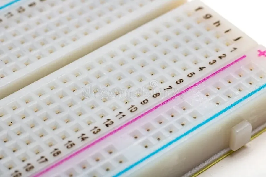
Breadboard closeup
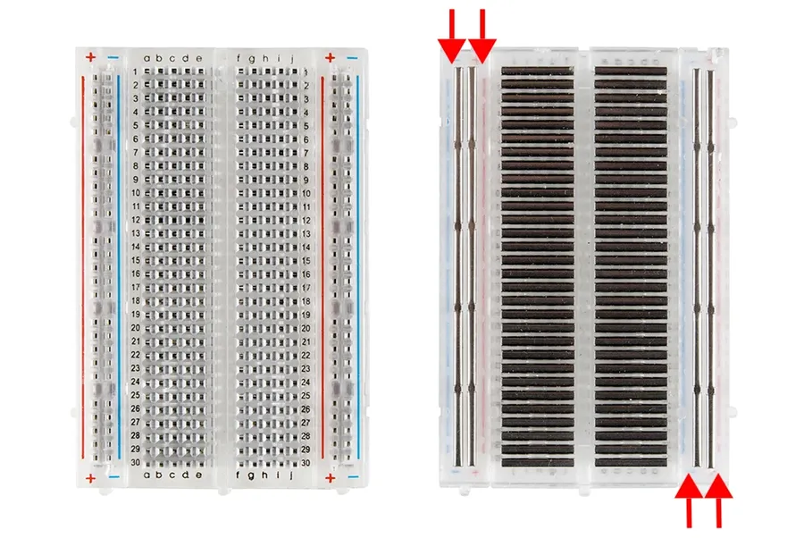
A breadboard is a fundamental prototyping tool in electronics, enabling the construction of temporary circuits without soldering. It consists of a matrix of interconnected sockets that allow for easy insertion and removal of electronic components, facilitating experimentation and circuit design iteration. Understanding the internal structure of a breadboard is key to using it effectively.
Terminal Strips These are the main areas where you insert electronic components like resistors, LEDs, and ICs. They are typically arranged in columns, and each column is internally connected, meaning that anything placed in the same column will be electrically connected. However, there is no connection between columns across the central channel of the breadboard.
Power Rails Located along the sides of the breadboard, these strips are typically marked with '+' and '-' symbols. They are used to provide consistent power and ground connections throughout the circuit. The power rails are internally connected vertically, making it easy to supply power to various parts of the circuit.
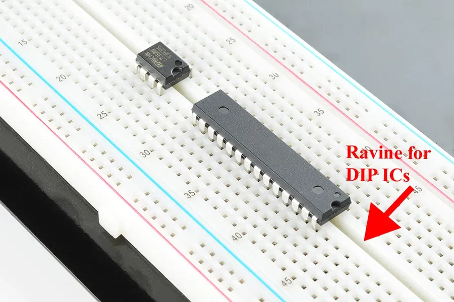
Central Channel The groove that runs down the middle of the breadboard isolates the terminal strips on either side, preventing short circuits and enabling ICs to be properly mounted.
Internal Connections Internally, the breadboard consists of metallic spring clips below each hole. When components are pushed into the holes, these clips grab their leads, creating an electrical connection. This design allows for easy component insertion and removal, making breadboards highly reusable.
Feature
Description
Terminal Strips
Columns of interconnected sockets for component placement.
Power Rails
Vertical strips for power and ground distribution.
Central Channel
Divides the terminal strips and allows for IC mounting.
Internal Connections
Metallic spring clips providing electrical contact.
Essential Tools and Components for Breadboarding
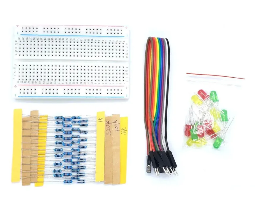
Breadboard components
Effective breadboarding relies on a set of fundamental tools and electronic components. These facilitate the construction, modification, and testing of electronic circuits, ranging from simple to complex designs. Selecting the appropriate tools and components is crucial for achieving reliable and efficient breadboarding outcomes.
Tool/Component
Description
Purpose
Selection Considerations
Jumper Wires
Insulated wires with rigid pins at both ends.
Connecting components on the breadboard and establishing electrical pathways.
Choose solid-core for durability and ensure the correct gauge for current capacity.
Resistors
Passive components that resist electrical current.
Limiting current flow, voltage division, and setting bias conditions.
Select resistance values based on circuit requirements, and consider power rating to avoid overheating.
LEDs (Light Emitting Diodes)
Semiconductor light sources that emit light when current flows.
Indicating circuit activity, visual feedback, and creating lighting effects.
Match the LED's forward voltage and current to the circuit design, and incorporate current limiting resistors for safe operation.
Integrated Circuits (ICs)
Miniaturized electronic circuits on a semiconductor chip.
Implementing complex logic, amplification, and signal processing functionalities.
Choose ICs based on their functional requirements, package compatibility, and ensure their power supply specifications are met.
Power Supply
Provides the necessary electrical power for the breadboard.
Enables proper circuit operation by providing voltage and current.
Select a power supply with appropriate voltage and current ratings for your components; use batteries, USB supplies, or a bench supply
Multimeter
An electronic measuring instrument.
Measuring voltage, current, and resistance.
Choose one with accuracy appropriate for your measurements. Digital multimeters are recommended for general use.
Wire Strippers
A tool used to strip insulation from wires.
Preparing wires for connection by exposing the conductive core.
Select a wire stripper appropriate for the gauge of wire you use.
Step-by-Step Guide to Setting Up Your First Breadboard Circuit
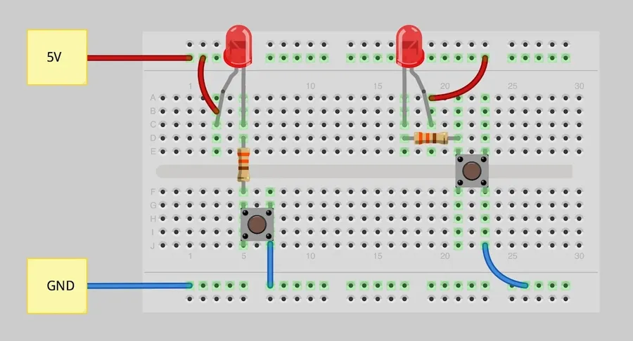
Breadboard circuit
Constructing your first circuit on a breadboard is a foundational skill in electronics. This section provides a detailed, step-by-step guide, ensuring correct component placement, proper power connections, and effective testing to confirm circuit functionality. By following this tutorial, you'll gain practical experience in applying breadboard techniques.
Gather Your Components and Tools Before you begin, assemble all necessary items: the breadboard, a power source (e.g., a 9V battery with a clip or a 5V USB supply), jumper wires (solid core), a resistor (e.g., 220Ω or 330Ω), and an LED. Having everything ready will streamline the process.
Understanding the Breadboard Layout Observe the breadboard's structure: the two power rails (positive and negative, often marked with red and blue lines respectively) run lengthwise and terminal strips are typically arranged in rows and columns with internal connections. Each row is electrically connected, but rows are not connected to each other, also columns are internally connected. Use this information to plan component placements.
Connecting the Power Supply Connect the positive terminal of your power source to the positive power rail of the breadboard using a jumper wire. Likewise, connect the negative terminal to the negative power rail. This will establish the power distribution for your circuit.
Placing the Resistor Insert one leg of the resistor into a row on the breadboard. Select a row that is connected to the positive power supply for this. It doesn't matter if you have it on row A, B, C, D or E, as these are all internally connected. Do not place this resistor across the breadboard as these are not connected. Now that the resistor is connected to the positive power line, connect the other end of the resistor to another row of the breadboard.
Placing the LED Place the longer leg (anode or positive side) of the LED into the same row as the other end of the resistor, and the shorter leg (cathode or negative side) in a row close to the negative power rail, this allows for the circuit to be completed.
Completing the Circuit Use a jumper wire to connect the row with the LED's cathode to the negative power rail, therefore closing the circuit.
Testing the Circuit If the connections are correct, the LED should illuminate upon power being supplied. If not, double-check your wiring against each of the above steps and ensure that the circuit is fully connected without any loose connections. It may be necessary to replace the led if it is damaged. If no issues are seen and the led is confirmed as working then the power supply and resistor should be checked to see if they are working correctly.
Breadboard Wiring Techniques: Best Practices and Common Mistakes
Breadboard wiring techniques
Effective breadboard wiring is crucial for reliable circuit prototyping. This section outlines essential techniques to ensure your circuits function correctly and to avoid common errors that can lead to project delays or component damage. Mastering these practices significantly improves the efficiency and accuracy of your breadboarding efforts.
Neat and Organized Wiring Employ short, direct wire paths and avoid cluttering the breadboard with excessively long wires. This practice minimizes the risk of accidental shorts and makes troubleshooting easier. Use different colored wires to distinguish between power, ground, and signal paths which can be very helpful for visual debugging.
Proper Wire Preparation Ensure that jumper wires are properly stripped to the correct length to make good contact with the breadboard terminals without exposing too much bare wire which could touch adjacent components and cause a short circuit. The insulation should be flush with the breadboard for safety.
Component Placement Plan the physical layout of your components carefully before connecting any wires. Position components to minimize wire lengths and avoid overcrowding the board which could lead to connectivity issues and damage to components. Group related components together as much as possible.
Power Rail Connections Use the breadboard's power rails to distribute power (VCC or positive supply) and ground (GND or negative supply) throughout your circuit. Make sure to properly connect the power supply to the rails and avoid directly connecting components to the power supply without proper safety precautions. Use bypass or decoupling capacitors to minimize power supply noise.
Double-Check Your Work Before applying power to the circuit, always double-check your wiring and component placement. Verify that all connections are correct and that the components are oriented properly. Use a multimeter to test for shorts or proper voltage readings to ensure there are no critical faults in the system. This is especially important for ICs as their incorrect wiring may cause irreversible damage.
Troubleshooting Strategies Systematically approach troubleshooting by starting with the power connections and then moving to other critical parts of the circuit. Use a multimeter or oscilloscope to test voltages, currents, and waveforms. Isolate the possible problem area of the circuit for focused testing, do not rewire the whole system unless necessary.
Avoiding Common Mistakes Be aware of common pitfalls such as accidental shorts due to exposed wire ends, incorrect component orientations (especially LEDs and polarized capacitors), and loose connections which can cause intermittent system issues. Follow basic safety protocols to avoid damaging your components or causing injury.
Powering Your Breadboard: Options and Safety
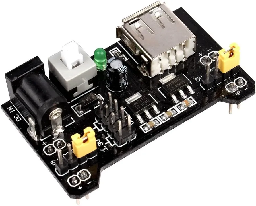
Breadboard power module
Powering a breadboard circuit correctly is crucial for its functionality and safety. Various power sources can be used, each with its own advantages and considerations. It's essential to understand these options and adhere to safety guidelines regarding voltage and current to avoid damaging components or causing hazards.
Batteries Batteries are a convenient power source for portable breadboard projects. Common options include 9V batteries, AA, and AAA batteries. When using batteries, ensure you check the voltage requirements of your circuit and choose a battery with the appropriate voltage output. For a simple circuit, a 9V battery may be sufficient, but for higher-power circuits, using multiple batteries or a different power source is often required. Be sure to pay attention to battery polarity, connecting the positive (+) terminal to the breadboard’s positive power rail and the negative (-) terminal to the breadboard’s ground rail.
USB Power USB power is widely accessible from computer ports or USB wall adapters, providing a stable 5V DC supply. This is suitable for many low-voltage breadboard circuits that are typically used for simple logic circuits and microcontroller projects. For connecting USB power, you can use a USB breakout board or a USB cable with stripped wires, ensuring correct polarity. However, USB power is limited in current, so it is not suitable for high-power applications. USB ports are typically limited to 500mA to 2A.
Bench Power Supplies Bench power supplies offer adjustable voltage and current control, making them versatile for various breadboard projects, including those requiring different voltage levels. A bench power supply allows you to set specific voltage and current limits based on your circuit needs. When using a bench power supply, exercise caution and ensure you set the proper voltage and current limits. Always measure the voltage of the output of your power supply before powering your circuit. Proper handling and setup are essential to prevent damage and ensure the reliable operation of your projects. Most bench power supplies have built-in short circuit protection. Always measure your circuit voltage and current requirements prior to connecting your power supply.
Power Source
Voltage
Current Capacity
Pros
Cons
Batteries
1.5V to 9V (or multiples)
Varies (depending on size and type)
Portable and convenient
Limited current, can drain quickly
USB Power
5V
Up to 2A
Commonly available, stable voltage
Limited current, may not support all circuits
Bench Power Supply
Adjustable (typically 0-30V)
Adjustable, typically several Amps
Versatile, precise control
Less portable and more expensive
Safety is paramount when powering a breadboard circuit. Always double-check your voltage and current requirements before connecting a power source. Exceeding these specifications can result in component failure or potential safety risks. When working with power supplies, start with lower voltage settings, gradually increasing if necessary. Use a multimeter to confirm the voltage and polarity of connections, especially with batteries. When using a power supply, ensure to set the desired voltage and current limit and confirm it with a multimeter before connecting to your circuit. Follow these precautions for every project to ensure safe breadboarding practices.
Advanced Breadboarding Techniques: Working with ICs and Microcontrollers
Breadboard IC and microcontroller
Moving beyond basic components, integrating Integrated Circuits (ICs), microcontrollers, and sensors into breadboard circuits dramatically expands the possibilities for project development. This section provides a guide to these advanced techniques, enabling users to prototype more complex and sophisticated electronic systems.
This section assumes a foundational knowledge of basic breadboarding techniques, as covered in prior sections. Focus here will be on the practical integration of more complex components.
Integrating Integrated Circuits (ICs) ICs, such as operational amplifiers (op-amps), timers (e.g., 555 timer), and logic gates, are fundamental to complex circuit design. Properly identifying the pinout of the IC (usually available in the datasheet) is crucial to its correct integration on the breadboard. Note the correct orientation is required for proper function (usually a notch or a dot indicates pin 1).
Working with Microcontrollers on a Breadboard Microcontrollers like Arduino or ESP32 can be readily interfaced with breadboards to create interactive systems. This requires understanding the specific power requirements and pin configurations of the chosen microcontroller. Additional support components such as bypass capacitors are important for stable operation and should be placed close to the microcontroller's power pins.
Interfacing Sensors Various sensors, including temperature sensors, light sensors, and accelerometers, can be connected to breadboard circuits using jumper wires. These sensors typically have specific power and signal requirements, as well as analog or digital outputs that need to be processed by an IC or a microcontroller. Always reference datasheets to confirm electrical requirements of any sensor.
Component Type
Considerations
Common Examples
Integrated Circuits (ICs)
Pinout diagram, proper orientation, power requirements, bypass capacitors
Power requirements, Pin configurations, programming interface, support circuitry
Arduino Uno, ESP32, PIC Microcontrollers
Sensors
Power requirements, Output type (analog/digital), specific pin configurations
Temperature (TMP36), Light (photodiode), Accelerometer (ADXL345)
Careful planning and referencing datasheets is vital to the successful integration of these advanced components. The breadboard provides flexibility to iterate and refine your designs before moving to a more permanent solution.
Frequently Asked Questions about Breadboard Electronics
This section addresses common queries regarding breadboard electronics, offering clear and concise answers based on engineering principles and practical experience. It will cover the purpose of breadboards, their suitability for beginners, their modern relevance, and their use by professional electrical engineers.
What is a breadboard used for in electronics? A breadboard is a solderless prototyping tool used to build and test electronic circuits. Its matrix of interconnected sockets allows for easy component insertion and removal, enabling rapid circuit design and experimentation without the need for soldering.
Are breadboards good for beginners? Yes, breadboards are exceptionally beneficial for beginners. They provide a risk-free and flexible environment to learn basic electronics concepts, circuit building, and troubleshooting techniques. The absence of soldering makes it easy to adjust circuits and correct errors quickly.
Are breadboards still used in modern electronics? Absolutely. Breadboards are not only a teaching tool; they are also widely used by professional engineers for prototyping and testing new circuit designs. They offer a convenient, reusable, and quick way to iterate on designs before committing to a printed circuit board (PCB).
Do electrical engineers use breadboards in their professional work? Yes, electrical engineers routinely use breadboards for prototyping and testing. This approach enables rapid verification of circuit functionality before moving to more permanent circuit implementations. This method reduces the risk of costly errors and allows for iterative design improvements.
Can breadboards handle high voltage or current applications? Breadboards are not designed for high voltage or current applications. They are primarily used for low-power circuits. Exceeding their limitations can cause damage to the board, components, and pose safety risks. Therefore, it is crucial to adhere to component specifications and never use breadboards for high-power circuits.
What are the common limitations of breadboards? Common limitations include limited current capacity, susceptibility to loose connections, and the introduction of parasitic capacitance and inductance due to the internal matrix and wiring. These effects can impact the behavior of high-frequency circuits. Breadboards are best suited for low frequency and low power applications.
Can I use a breadboard for my final project? While possible, using a breadboard for a final project is generally not recommended. Breadboards are designed for prototyping and testing. For final applications, a more reliable and robust solution such as a Printed Circuit Board (PCB) is preferred. PCBs provide secure component mounting and stable connections, especially when subjected to use. Transitioning to PCBs is an essential step after validating a design on a breadboard.
Breadboard Comparison: Choosing the Right Breadboard for Your Needs
Selecting the appropriate breadboard is crucial for effective prototyping. Breadboards vary in size, layout, and features, each influencing suitability for different project complexities. Understanding these differences will lead to better project management and reduce potential pitfalls.
Feature
Small Breadboard
Medium Breadboard
Large Breadboard
Breadboard Kit
Size
Typically ~30 columns, 17 rows.
Typically ~60 columns, 30 rows.
Typically ~80+ columns, 60+ rows.
Varies greatly depending on kit.
Power Rails
Often single, or none.
Usually two, sometimes split.
Typically two or more, split sections.
Often includes multiple power rails and distribution blocks.
Best Use Cases
Simple circuits with few components. Great for beginners.
Intermediate circuits, more components, moderate complexity.
Complex circuits with multiple ICs and sub-circuits. Advanced projects.
A range of projects from simple to complex, often contains all the necessary components to get started quickly.
Cost
Low cost, budget-friendly option.
Moderately priced.
Higher cost due to larger size.
Variable pricing depending on the quantity and quality of included components.
Portability
Highly portable, ideal for mobile work.
Reasonably portable.
Less portable due to larger size.
Varies with the type of packaging for the kit. Can range from small boxes to larger cases.
Accessories
Generally fewer accessories.
May include basic jumper wires.
Often includes integrated binding posts for power.
Often includes jumper wires, LEDs, resistors, capacitors, and sometimes ICs and microcontrollers.
Breadboard kits frequently include essential components such as jumper wires, resistors, LEDs, capacitors and sometimes microcontrollers. The value of these kits is often in the time they save a user in component selection, making the start of a project faster, they are ideal for people who are new to electronics or prototyping.
Transitioning from Breadboard to Permanent Circuits: A Practical Guide
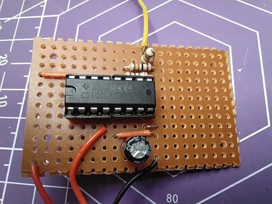
Perfboard circuit
While breadboards are invaluable for prototyping and testing electronic circuits, they are not designed for long-term use. Once a circuit design is validated on a breadboard, transitioning to a permanent circuit ensures reliability and stability. This section provides a practical guide on moving your breadboard projects to more durable and lasting solutions.
The transition process typically involves two main stages: selecting the appropriate permanent circuit medium and then transferring the breadboard layout to the chosen medium. The following are common methods for creating permanent circuits.
Stripboard (Veroboard) Stripboard, also known as veroboard, is a versatile prototyping board with parallel copper tracks. It's suitable for simple to moderately complex circuits. Components are soldered onto the board, and tracks can be cut to create the desired circuit paths. This process can involve some planning, but is generally straightforward.
Perfboard Perfboard, or protoboard, consists of a grid of holes. Components are placed and wired using point-to-point soldering. This is less structured than stripboard and is more suitable for circuits with complex shapes. However, layout planning can be more challenging on perfboard than on stripboard.
Printed Circuit Board (PCB) For more professional or mass-produced circuits, PCBs are the ideal choice. PCBs are custom-designed boards with copper traces etched to connect the components. Designing PCBs requires specialized software but offers the most robust and reliable solution. PCBs are ideal when repeatability and high reliability are desired.
Transferring a circuit from a breadboard to a permanent medium involves carefully mapping the breadboard connections to the new layout. Here are the steps for a typical transition:
Document Your Breadboard Layout Before disassembling your breadboard circuit, create a detailed diagram of how the components are connected. Use a notebook, a circuit simulation program, or a picture for reference. This is an essential step, particularly with complex circuits.
Plan Your Permanent Layout Based on your breadboard layout and the type of permanent circuit medium you've chosen, plan how the components will be positioned and wired or connected. Consider the physical space requirements and any necessary design changes, such as component orientation.
Assemble the Permanent Circuit Follow your layout diagram to place the components on the stripboard, perfboard or PCB and then connect them using soldering or by other means suitable to your selected media. Double-check all connections to minimize errors.
Test Your Permanent Circuit After assembly, meticulously verify your connections using a multimeter. Then, power up the circuit to confirm it functions as expected. Troubleshoot any issues systematically, starting with the most likely causes such as bad connections or misplaced components.
Feature
Stripboard
Perfboard
PCB
Structure
Parallel Copper Strips
Grid of Holes
Custom Etched Traces
Complexity
Simple to Moderate
Moderate to Complex
Any Complexity
Ease of Use
Relatively Easy
Moderate
Requires Design Software
Durability
Moderate
Moderate
High
Cost
Low
Low
Higher, more so with short runs
Best for
General Circuits
Complex and Unique Circuits
Professional/High-Volume Circuits
Breadboard electronics form a vital part of the journey for any electronic enthusiast, offering a safe, flexible, and educational platform to test ideas and develop circuits. Understanding these concepts not only improves prototyping but also strengthens the basic knowledge of circuit design, encouraging a deeper exploration into the world of electronics and providing a sound foundation for advanced projects.