From the humble beginnings of the transistor to the sophisticated electronics of today, the 2N3055 has remained a reliable workhorse. Imagine the sound of a classic guitar amplifier or a powerful motor in operation; chances are the 2N3055 transistor played a pivotal role. This article delves into the world of the 2N3055, exploring its specifications, applications, and why it remains a popular choice for both hobbyists and professionals.
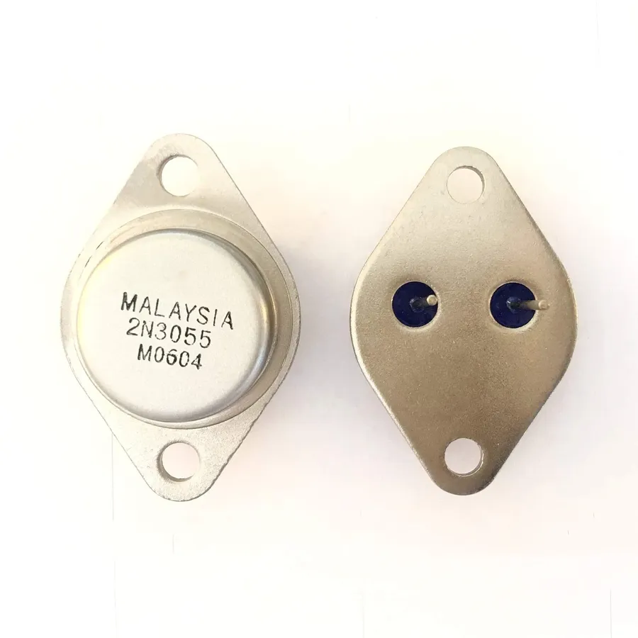
The 2N3055 is a ubiquitous NPN power transistor, renowned for its reliability and robustness since its introduction by RCA in the early 1960s. Its enduring popularity stems from its capability to handle significant current and voltage, making it a cornerstone in a multitude of electronic applications.
Originally designed for audio amplification, the 2N3055's ability to deliver substantial power led to its adoption in diverse fields. Its design and specifications are indicative of the era in which it was created, utilizing a TO-3 package that effectively manages thermal dissipation, which is crucial for power transistors.
The 2N3055's success is not just in its technical performance but also in its ease of use and wide availability, making it a staple in both hobbyist and professional electronics projects. The transistor's longevity on the market is a testament to its effective design and utility in practical applications, highlighting its crucial role in the evolution of power electronics.
The 2N3055 is a silicon NPN power transistor renowned for its robust performance in various electronic applications. A thorough understanding of its technical specifications is paramount for engineers and hobbyists alike to ensure proper implementation and avoid potential component failure. This section details the key parameters that define its operational capabilities.
| Parameter | Symbol | Value | Unit |
|---|---|---|---|
| Maximum Collector Current | IC(max) | 15 | A |
| Maximum Collector-Emitter Voltage | VCEO(max) | 60 | V |
| Maximum Collector-Base Voltage | VCBO(max) | 100 | V |
| Maximum Emitter-Base Voltage | VEBO(max) | 7 | V |
| DC Current Gain (Typical) | hFE | 20-70 | - |
| Power Dissipation at 25°C | PD(max) | 115 | W |
| Operating Junction Temperature | TJ(max) | 200 | °C |
| Storage Temperature | TSTG | -65 to +200 | °C |
It's important to note that these values represent the absolute maximum ratings. Operating the transistor consistently at or near these limits can drastically shorten its lifespan and could lead to device failure. For optimal reliability, circuits should be designed such that the transistor operates well below these maximum thresholds.
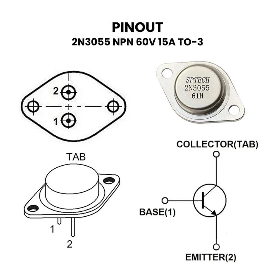
The 2N3055 transistor is typically housed in a TO-3 package, characterized by its robust metal casing designed for efficient heat dissipation. Understanding the pin configuration—the base, collector, and emitter terminals—is fundamental for proper integration into any electronic circuit.
Each terminal plays a critical role in the transistor's operation. The base terminal controls the current flow between the collector and emitter. A small current applied to the base can regulate a much larger current flowing through the collector-emitter path, which is the core principle of transistor amplification and switching applications.
| Pin Number | Terminal Name | Description |
|---|---|---|
| 1 | Base (B) | The control terminal. A current applied here regulates the collector-emitter current. |
| 2 | Emitter (E) | The terminal from which current flows out of the transistor. |
| Case | Collector (C) | The terminal through which current flows into the transistor; usually connected to the TO-3 case. |
When mounting the 2N3055 in the TO-3 package, it's vital to note that the metal case itself serves as the collector terminal. This connection provides excellent thermal conductivity, which helps in heat management. Appropriate use of thermal compounds or insulators may be necessary depending on the specific thermal requirements of the application. For correct circuit implementation, adhere to this configuration, with proper orientation which is very important for preventing damage to the transistor.
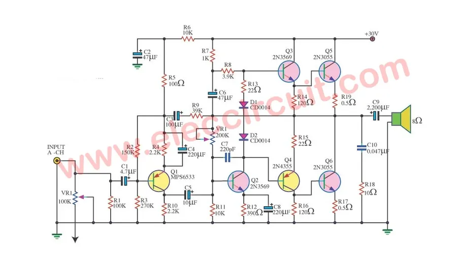
The 2N3055 transistor, a workhorse in power electronics, finds extensive use across various applications due to its robust characteristics and reliability. Its capacity to handle significant current and power makes it suitable for both linear and switching applications. Below are some key areas where the 2N3055 demonstrates its utility.
These applications underscore the 2N3055's versatility and reliability in power electronics. Its widespread adoption in both hobbyist and professional electronics further establishes its position as a cornerstone component in the field.
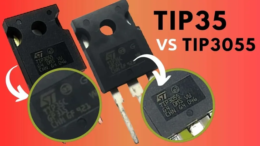
The 2N3055 and TIP3055 are both NPN power transistors commonly used in various electronic applications, but they differ in several key aspects. Understanding these differences is essential for selecting the appropriate transistor for a given circuit design. This section provides a detailed comparison of their package, electrical characteristics, and typical usage scenarios.
| Feature | 2N3055 | TIP3055 |
|---|---|---|
| Package | TO-3 (Metal Can) | TO-247 or TO-218 (Plastic) |
| Maximum Collector Current (Ic) | 15A | 15A |
| Maximum Collector-Emitter Voltage (Vceo) | 60V | 60V - 100V (depending on variant) |
| DC Current Gain (hFE) | 20-70 | 10-50 (typically lower than 2N3055) |
| Power Dissipation (Pd) | 115W - 150W | 90W - 150W (depending on variant) |
| Operating Temperature | -65°C to +200°C | -65°C to +150°C |
| Thermal Resistance (junction-case) | 1.5°C/W (TO-3) | 1.2°C/W (TO-247) |
| Typical Applications | Power Supplies, Audio Amplifiers, General Purpose | Switching Regulators, General Purpose |
| Cost | Generally Higher | Generally Lower |
| Mounting | Requires mounting hardware and mica insulation | Often mounted directly on heatsink |
The 2N3055's TO-3 metal package offers superior heat dissipation capabilities due to its direct contact with a heatsink when mounted correctly using thermal grease and a mica insulator. The TIP3055, typically in a plastic TO-247 or TO-218 package, is generally more cost-effective and offers greater ease of mounting. The plastic packaging however, usually results in a slightly lower maximum operating temperature. Both transistors share similar current and voltage handling capacities, but the 2N3055 tends to have a higher typical DC current gain (hFE) value, making it a suitable for high gain applications, while the TIP3055 is often selected for cost-sensitive switching applications and can have various maximum voltage ratings.
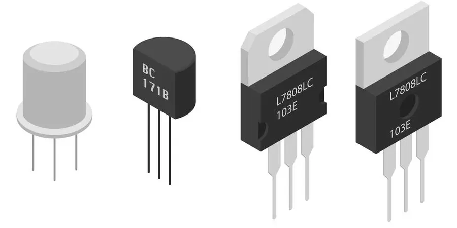
The 2N3055, while a robust and widely used NPN power transistor, may not always be readily available. Therefore, understanding its equivalents and suitable replacements is crucial for project continuity and flexibility in circuit design. Several transistors offer comparable performance characteristics, allowing for seamless substitution in various applications.
| Original Transistor | Equivalent Transistors | Key Characteristics | Application Notes |
|---|---|---|---|
| 2N3055 | MJ2955 | PNP Complementary, Similar Power Ratings | Often used as a complementary pair in push-pull amplifiers and power control circuits |
| 2N3055 | TIP3055 | Similar Characteristics, Different Package (Plastic) | A cost effective replacement, but may require different heat sinking methods |
| 2N3055 | 2SC5200 | Higher Voltage and Current Ratings | Suitable for high-power applications where the 2N3055's limits are reached |
| 2N3055 | 2SD1047 | Similar Voltage and Current Ratings | General purpose substitution in medium to high power applications. |
When selecting an equivalent transistor, carefully consider parameters such as maximum collector current, collector-emitter voltage, power dissipation, and hFE (DC current gain). These should match or exceed the original 2N3055's specifications to maintain the desired performance and reliability of the circuit. Always consult the datasheets of both the 2N3055 and the potential replacement to ensure compatibility.
This section addresses common queries regarding the 2N3055 transistor, offering clear, concise answers to assist users in understanding its applications, alternatives, and characteristics. We've compiled questions based on user searches and common points of confusion to provide a comprehensive guide.
Effectively utilizing the 2N3055 transistor requires careful consideration of several practical aspects to ensure reliable operation and prevent damage. This section offers actionable advice on heat dissipation, biasing, and circuit design tailored for the 2N3055.
The 2N3055 transistor stands as a testament to enduring engineering. Its robust design and versatile applications have made it a staple in electronics for decades. As we continue to innovate in the realm of technology, understanding the fundamental role of components like the 2N3055 is essential. Whether you're a seasoned engineer or a budding hobbyist, mastering the application of the 2N3055 empowers you to bring your electronic projects to life.

